
What is the ER Model?
ER model, short for entity-relationship model, is a diagram type that shows real world objects, their characteristics, and the relationships they have with one another. ER diagrams are used as blueprints for developers when creating databases. ER diagrams provide a visualized model that is easy to read and understand. There are several diagramming styles, called notation types, dedicated to the creation of ER diagrams.
Make your own ER diagram in Gleek.
The ER model consists of entities, attributes, cardinality, and relationships, which are shown with specific symbols, based on the notation type the diagram was made in. To learn more about notation types, read our guide to ER notations and symbols.
Common ER model symbols
Entities: Entities are real world objects, or objects within the database. They’re usually depicted in a rectangle. Entities can be tangible, intangible, strong, or weak, depending on the notation type.
Arrows: Arrows indicate the relationships that entities share. ER relationships can either occur one time, or more than once.
Attributes: Attributes are details or characteristics that define entities. Depending on the notation type, they can either be listed in the entity, or in a diamond or oval shape. Attributes can be simple, composite, derived, or single/multi valued.
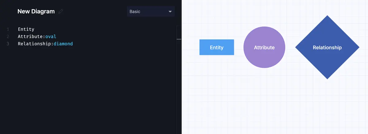
ERD components: Entity, Attribute and Relationship.
Common ER model notations:
Chen notation: One of the most common ER notations, Chen notion is a highly detailed way of expressing the relationships, attributes, and strengths of entities within the database. Chen notation has many ways of expressing details about all of the components in the diagram.
Crow notation: Also known as crow’s foot notation, this style focuses on multiplicities, which is the number of times an instance can associate with other instances.
Read a detailed comparison of Chen and Crow’s foot notations.
Arrow notation: With arrow notation, emphasis is placed on the relationships between entities, and how many times those instances occur. In arrow notation, relationships are defined as one to one, one to many, many to one, or many to many.
UML notation: UML, meaning Unified Modeling Language, is a popular pictographic language used in ER diagrams, as well as other diagram types. It is easy to understand, and gives information about relationship instances, along with entities and attributes.
What is the Relational Model?
The relational model was developed in 1970 by EF Codd as a way to model data in a table format, rather than as a diagram. Instead of focusing on the relationships and instances between entities, tables in the relational model show relevant data, how each table is related.
In relational models, Structured Query Language (SQL) is used instead of UML or other notation types. ER model and relational model are similar in that they both convey information in a database, but how data is shown is quite different.
Relational model concepts
Instead of entities and attributes, relational models have these components.
Table: A database is made up of many tables, each with different data.
Relation: Relations are also known as files or tables, and contain domains, columns, and rows.
Domain: Domains are like entities, and can have many attributes, or columns.
Column: Columns are attributes, and show the type of data represented. For example, under a column called ‘student names’, you will only find the names of the students entered into the table.
Record: Records, rows, or tuples, are all of the attributes of a certain piece of data. Unlike columns that show all of the domains of a specific type, records show all of the data associated with one column entry. In the ‘student names’ column you might find John Smith, and in the record for John Smith, you can find all of the data pertaining specifically to John.
Degree: The degree of a table is the number of attributes listed.
Make your own ER diagram in Gleek.
Differences between ER model and relational model
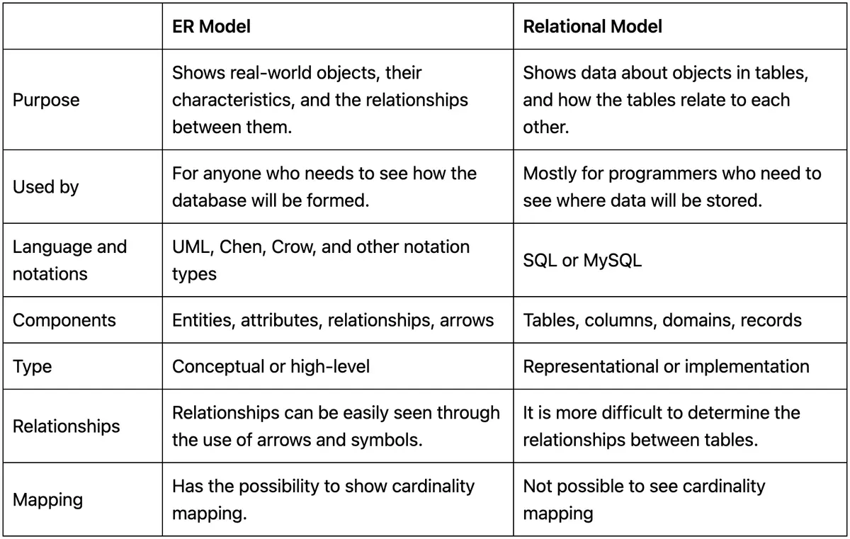
The ER model’s main focus is on entities, and how they interact with each other. The relational model is more focused on information, and tables with related data make up the database.
The relational model is a representational or implementation model, and ER models are conceptual or high-level models.
ER models contain entities, relationships, and attributes. Relational models are mode of tables, records, and domains.
It is not possible to see cardinalities in the relational model, but it is in the ER model.
ER diagrams are often converted into relational schemas to better show the data.
Do you need to change your ER model into a relational model? Read our post on how to convert an ER diagram into a relational schema.
Make your own ER diagram in Gleek.
ERD vs Relational schema
Making diagrams can be time confusing or just downright confusing sometimes. For those ER diagrams you need in a flash, try Gleek. Gleek is a text-based diagramming tool that can be used to quickly make ER diagrams, along with many other types, just by using your keyboard. Using Chen or Crow notation? No problem! Gleek supports both of these notation styles. Try Gleek for free and get creative.
Related posts
ER diagram example: online shopping system (Crow’s Foot notation)
UML vs. ER diagrams: A detailed comparison
How to represent a weak entity in ER diagram
Crow’s foot notation in entity-relationship diagrams
Derived Attributes in ER diagrams: A comprehensive exploration
Enhanced entity-relationship diagram: features and components
What is data modeling? Types & process
Quick guide to physical data modeling
ER diagram for a hospital management system (Crow’s Foot notation)