
ER diagrams vs. EER diagrams
Developers use entity-relationship diagrams to sketch out designs for databases. As their name suggests, enhanced entity-relationship diagrams take ER diagrams a step further and allow for much more complex designs for modern databases. EER diagrams give developers the tools to add detail and better understand how their database should be designed.
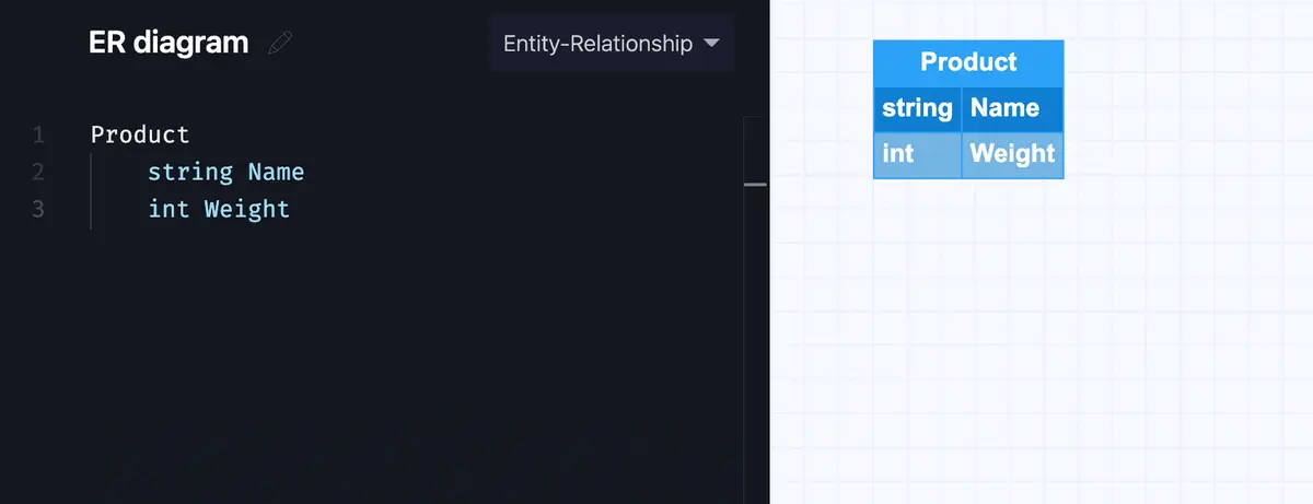
ER diagrams use three basic elements to represent databases: entities, attributes, and relationships. Entities are the real-world objects or concepts that are relevant to the database. For instance, here’s a very simple entity in the Gleek app.
Make your own ER diagram in Gleek.
Attributes are the characteristics of entities. Attributes can be simple, composite containing several simple attributes, or derived from other attributes. Let’s give our product the attributes name and weight. In a real database, such as one powering an online store, you can imagine that products would have many attributes. An attribute can be either a string, or a sequence of characters, or an integer, i.e. a sequence of numbers.
Read our detailed guide on how to create an ERD for E-commerce website.
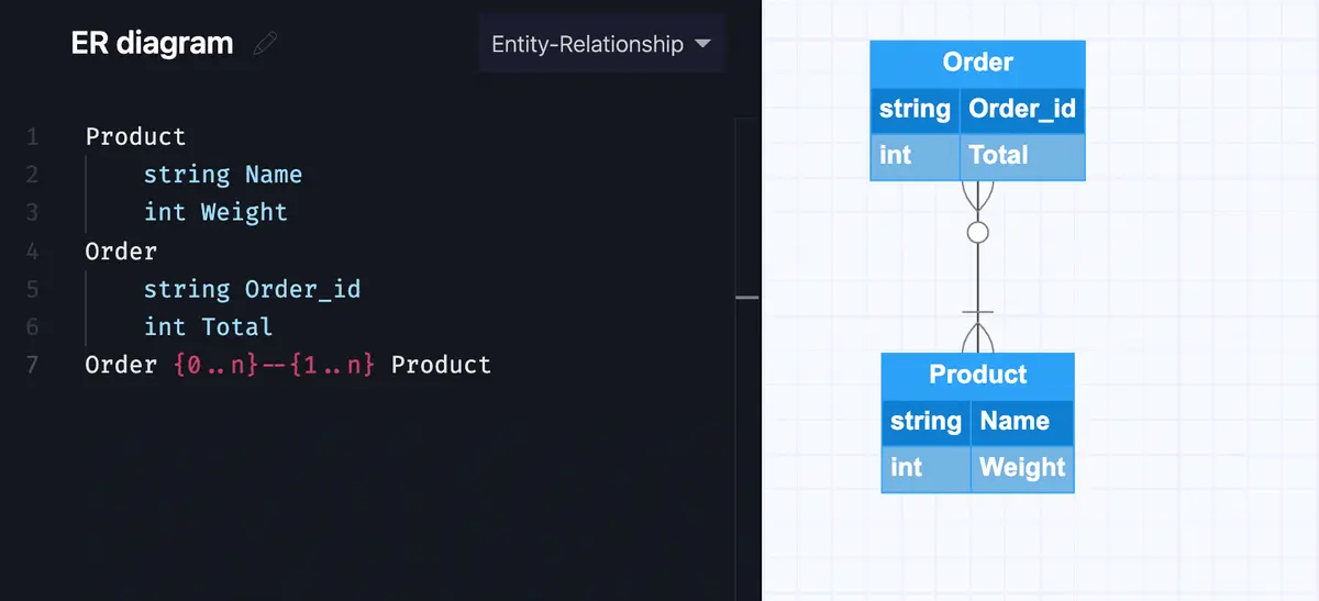
Relationships show how the entities in the database relate to each other. We can add another entity to our simple diagram to show a straightforward many-to-one relationship where an order can contain one or many products while a product can be added to zero or many orders.
Make your own ER diagram in Gleek.
That should give you an idea of how an entity-relationship diagram is put together. If you want to explore the basics of ER diagrams further, you can check out this page. ER diagrams can be represented by either Crow’s Foot notation, as in our quick example above, or Chen notation. We’ll come back to this later on!
Related post: ER diagram example for online shopping system using Crow’s Foot notation
What are the components of the EER diagram?
Now that we’ve refreshed your memory on ER diagrams, what extra components and features do EER diagrams offer a database designer?
Generalization and specialization
The first extra tool in the EER toolbox is the concept of generalization and specialization when it comes to entities. If an entity is a specialized type, or class, of another entity, it will often be useful to designate it as a subclass of that entity. The reverse process, of identifying generalized types, or classes, leads to the creation of superclasses.
Subclasses and superclasses
EER diagrams enable a developer to create meaningful subgroupings of entities in the database. Subclasses, or subtypes, and superclasses, or supertypes, can be thought of as useful ways to describe similarities in the entities represented. For instance, Employee would be an effective superclass in an online grocery delivery company, with roles such as Executive, Secretary, Stock Picker, or Driver all behaving as subclasses of Employee. Each of these positions will share many of the attributes of the superclass, such as EmployeeID, Name, Salary, Address, Phone number, and they will inherit these attributes from the superclass.
That brings us to the next powerful feature of EER diagrams: inheritance. Because subtypes or subclasses inherit their attributes and relationships from the superclass, the database designer can represent complex, hierarchical interdependencies within the system being described. The process does not travel in the other direction, so superclasses are not affected by additional attributes or relationships only assigned to subclasses.
Constraints
Additional control can be exerted over the generalization and specialization used in an EER diagram by using constraints. These can be divided into disjointness constraints, overlapping constraints, and completeness constraints.
Disjointness constraint means that an instance of a superclass can only be a member of one subclass. For instance, a bank database might have an “Account” superclass, with subclasses “Current Account” and “Savings Account”. These two subclasses must be disjoint, in that an instance must be one or the other and cannot be both.
Overlapping constraint means that an instance of a superclass can be a member of multiple subclasses. For instance, in our online grocery store database, the superclass “Employee” could have instances that overlapped into two different roles. A “Stock Picker” might also be rated as a “Driver” and therefore be able to exist in both subclasses.
Completeness constraint decides whether an instance of a superclass must be a member of at least one subclass. This can be further broken down into partial or total completeness. Partial completeness allows for some superclass instances not to be members of any subclass, while total completeness requires every superclass instance to be a member of at least one subclass.
UNION and category types
Finally, the EER diagram introduces the concept of a UNION type or category. This is used to identify a collection of entities that are the union of objects of different entity types. This collection forms a subclass that brings together distinct entity types. The category can be total or partial and inheritance can be selectively applied.
In our online grocery store example, we might have three superclasses, “Employee”, “Company”, and “Parent Company”. The online store also uses vehicles to make deliveries, and the database tracks the ownership of each vehicle. Each of the above entities can own a particular vehicle, as the store, which is a subsidiary of a larger company, also allows drivers to use their own vehicles for delivery. So we need to create a category “Owner” that is a subclass of the UNION of the three entity sets of Employee, Company, and Parent Company, to cover all the possible ownership scenarios.
Make your own ER diagram in Gleek.
What are EER diagrams used for?
You can see that EER diagrams give you a lot more control and detail than plain ER diagrams, but you might not be sure when you should opt for an EER diagram. The ER diagram is perfect for sketching out a conceptual design for a database, explaining your ideas to colleagues, or getting a solid visual overview of the database. A good rule of thumb is to go with EER as soon as you’re dealing with large amounts of data or when your database starts to become too complex to manage with an existing ER diagram. If you’re at that point where you don’t think you need an EER diagram yet, Gleek is there for you! Gleek fully supports both Chen and Crow’s Foot notation in ER diagrams and we’re adding more features every day. Check out this article on the difference between the two types of notation to help you decide which is for you and then read this introductory article on designing your database using the entity-relationship model.
Related posts
ER diagram example: online shopping system (Crow’s Foot notation)
Guide to entity-relationship diagram notations & symbols
How do you convert an ER diagram into a relational schema?
ER diagram for an E-commerce website with Gleek's AI chat
What is the entity-relationship diagram in database design?
Crow’s foot notation in entity-relationship diagrams
UML vs. ER diagrams: A detailed comparison
Crow’s Foot vs. Chen notation: detailed comparison for 2022
Composite and other attributes in the entity-relationship model
ER diagram for a hospital management system (Crow’s Foot notation)