
What is UML?
The Unified Modeling Language (UML) is a general-purpose modeling language used to visualize the design of a system. You can think of UML as a way to create blueprints so that software is fully understood by the designer before any coding begins.
Models assist developers by letting them initially work at a level of abstraction that helps them avoid pitfalls and optimize processes before programming. UML is a toolbox for creating such models and it incorporates a standardized system of notation and best practices suited to object-oriented design.
Make your own UML diagram with Gleek.
UML started out in the 1990s and it has gone through a number of iterations before arriving at the current version, UML 2. As a visual language used to represent the structure and behavior of the system modeled, UML is extremely useful in a business environment where developers need to communicate their ideas to stakeholders with less programming knowledge.
Types of UML 2 diagrams
UML 2 allows for fourteen different types of diagrams. Let’s briefly list these before moving on to explore the various relationships possible in UML.
UML diagrams divide neatly into two categories: structure diagrams and behavior diagrams.
Structure diagrams
Component diagram
Deployment diagram
Package diagram
Composite structure diagram
Profile diagram
Behavior diagrams
Use case diagram
Interaction overview diagram
Timing diagram
UML relationship types
Any UML diagram consists of model elements. These are the shapes you draw to represent the components, or building blocks, of the system you are describing. Relationships are also a type of model element. Relationships add information to your diagram by clarifying the way that elements interact or depend upon each other. They describe the behavior that is desired, or can be expected, between elements.
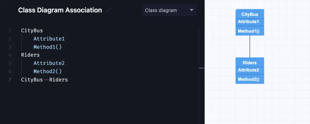
Association
This simply means that one model element is linked in some way to another model element. The association indicates the nature and rules that govern the relationship. The basic way to represent association is with a line between the elements.
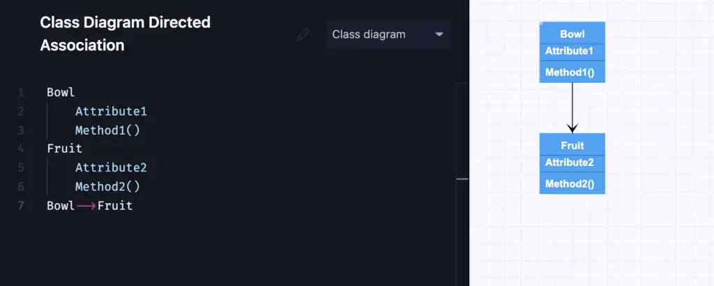
Association can be more complex, in that it can be directed, which is represented by an arrow showing the flow of control, or even reflexive, in cases where the element has a relationship to itself. In this case, the arrow loops back to the element.
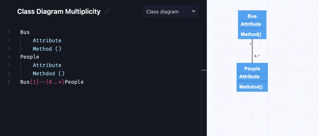
Multiplicity
An association relationship between elements can also have cardinality, for instance, one-to-one, one-to-many, many-to-one, or many-to-many, zero-to-many, and so on. This can also be shown in a label on the line.
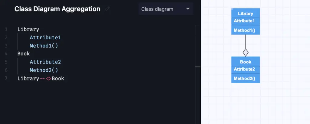
Aggregation
This type of association relationship indicates an element is formed by a collection of other elements. For instance, a company has departments or a library has books. The aggregate element relies on other elements as parts, but those other elements can also exist independently of it. An aggregation is represented by a line from one class to another, with an unfilled diamond shape near the aggregate, or the element that represents the class that is assembled by combining the part elements.
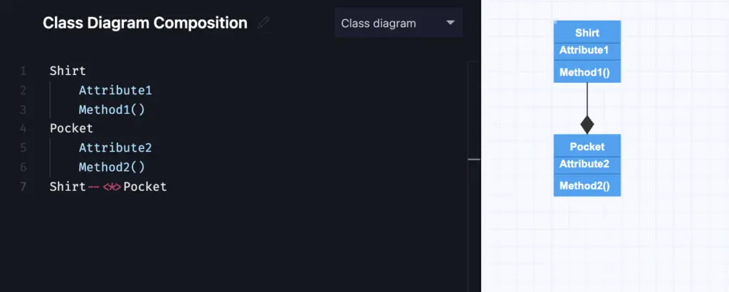
Another type of aggregation relationship, composition, is one in which the part elements cannot exist without the aggregate. For instance, the rooms in a house cannot continue to exist if the house is destroyed. For a composition relationship, a filled diamond is shown on the line near the aggregate.
Read on the differences between Aggregation and Composition relationships.
Dependency
Dependencies in UML indicate that a source element, also called the client, and target element, also called the supplier, are related so that the source element makes use of, or depends upon, the target element. Changes in the behavior or structure of the target may mean changes in the source.
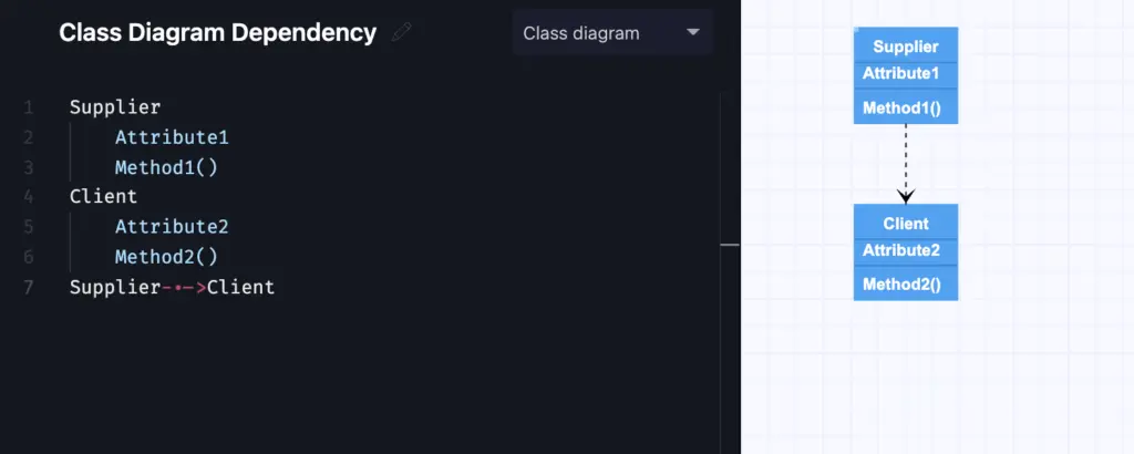
Dependency is shown as a dashed line from the source to the target, with an open arrowhead at the end of the line connected to the target element.
Generalization/Inheritance
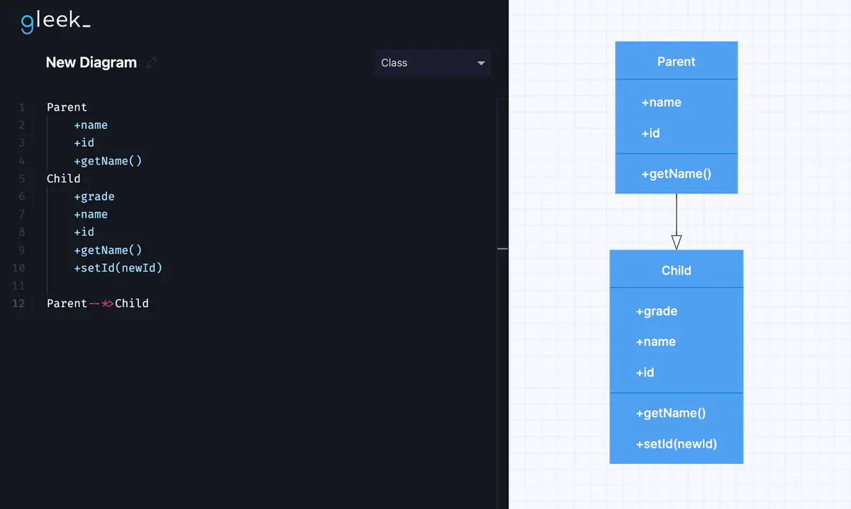
A generalization or inheritance relationship in UML can exist between a specific element and a more general element of the same kind. The specific element inherits the attributes, relationships, and other characteristics from the general element. Types, undifferentiated classes, implementation classes, and interfaces can all make use of generalized relationships. Generalization can be considered to be a parent-child relationship, where the child inherits from the parent and can therefore access and use the structure and behavior of the parent element.
Make your own UML diagram with Gleek.
Generalization is shown as a solid line from the specific element to the general element, with an unfilled arrow at the end of the line connected to the general element.
Realization
Realization is a relationship between two elements in a UML diagram where one element specifies behavior and the other element implements or executes, in other words, realizes, that behavior. Again, there is a source element, called the realization element, and a target element, called the specification element, and the relationship is also often referred to as being between a supplier and client. In many cases, the specification element will be an interface, or a collection of operations, with the realization element as the implementation of those behaviors or operations.
However, there is no assumption of inheritance in realization, as the relationship is rather that the source element supports, or realizes, the operations of the target element without any requirement to support other aspects such as attributes or associations. More than one client can realize the operations of a single supplier.
Realization indicates that the client supports all the operations of the supplier, so objects of the source class can be substituted for objects of other classes that also realize the same supplier.
Undifferentiated classes and implementation classes can act as a type and perform the function of an interface. Realization reuses the operations of types and interfaces, with the realization element realizing its specification elements.
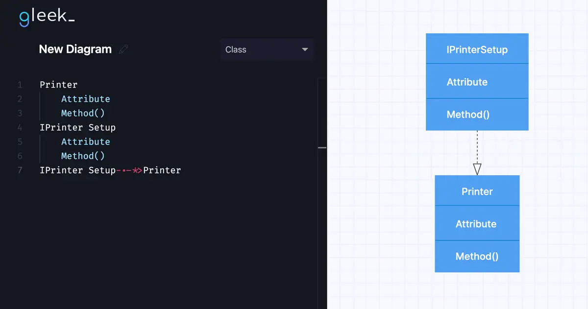
Realization is shown as a dashed line from the source to the target element, with an unfilled arrow at the end connected to the target element. Note that this is the canonical form of depicting a realization relationship. Realization can also be shown in elided form, where a solid line leads to a circle, otherwise known as lollipop notation, labeled as the target element.
Related posts
UML class diagram arrow types: explanations and examples
How do we create a Class diagram for a Library Management system?
Best 7 UML tools to use in 2021
UML vs. ER diagrams: A detailed comparison
Restaurant management system class diagram from scratch
Class diagram for an ATM system: step-by-step guide