What is a state diagram?
State diagrams, also known as state machine diagrams, belong to the family of behavioral diagrams in the Unified Modeling Language (UML). They are dynamic modeling techniques that depict the various states an object or interaction goes through during its lifecycle and the transitions between these states.
In the domain of computer science and related fields, state diagrams serve as an indispensable tool. They provide a visual representation of an object's behavior throughout its lifecycle, shedding light on the different states it can be in, the transitions between these states, and the events that trigger these changes. This makes them particularly useful for designing and understanding software applications, digital circuits, user interfaces, network protocols, and more.
Moreover, state diagrams play an important role when modeling reactive systems - systems that respond to specific internal or external events. These could range from hardware logic circuits to intricate business workflows. By visually representing the states and transitions in these systems, state diagrams offer a clear, concise method to comprehend and communicate how these systems function and react to different events.
State diagrams also facilitate communication between technical and non-technical stakeholders. They ensure everyone involved in a project - from developers and project managers to clients and end-users - comprehends the system's behavior. In summary, state diagrams are invaluable for anyone seeking to design, understand, or communicate complex system behaviors.
Components of the State Diagram
A state diagram in Gleek is composed of several key components, each contributing to the overall depiction of a system's behavior:
State
States are fundamental to any state diagram. They represent the different conditions an object or interaction can be in at any given time. Each state reflects a specific phase in the lifecycle of an object, defining its current condition based on its history or memory.
Initial State
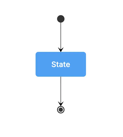
The initial state, usually represented by a filled black circle, indicates the starting point of the state diagram. It signifies the beginning of the lifecycle of the object or interaction.
Final State
The final state, often depicted as an encircled black circle, marks the end of the state diagram. It indicates the termination of the lifecycle of the object or interaction.
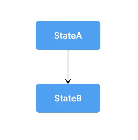
Transition
Transitions are represented by arrows that connect one state to another, denoting a shift or change in state. These transitions occur based on specific triggers, which could be an event, a condition, or the passage of time.
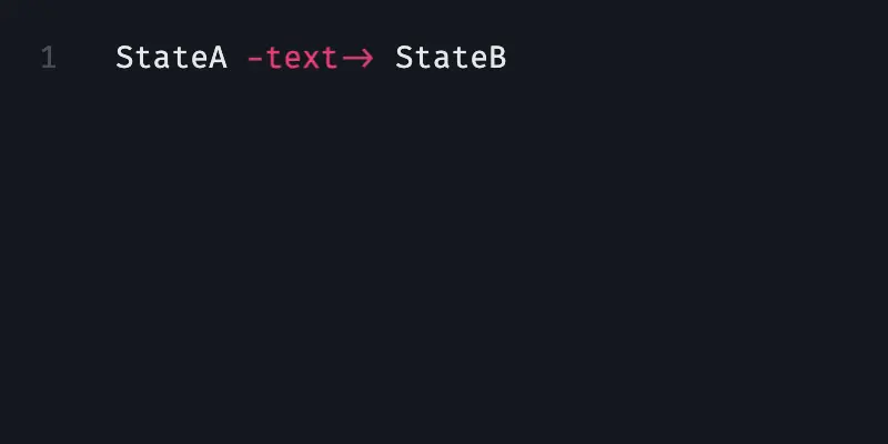
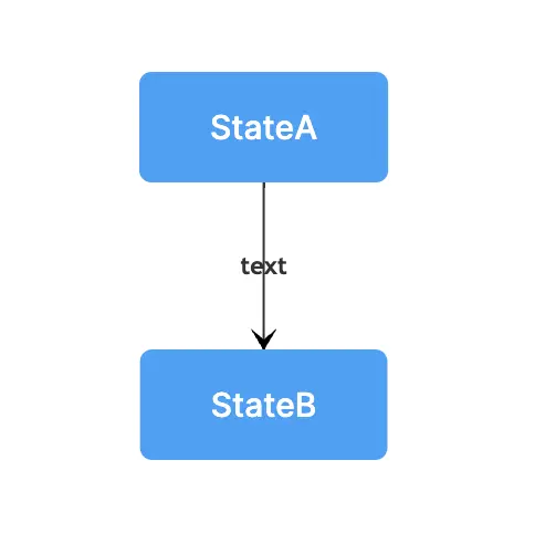
Text
Text labels provide additional context about the triggers for a transition or what occurs during a transition. They can include information about events, conditions, or actions that cause or result from the transition.
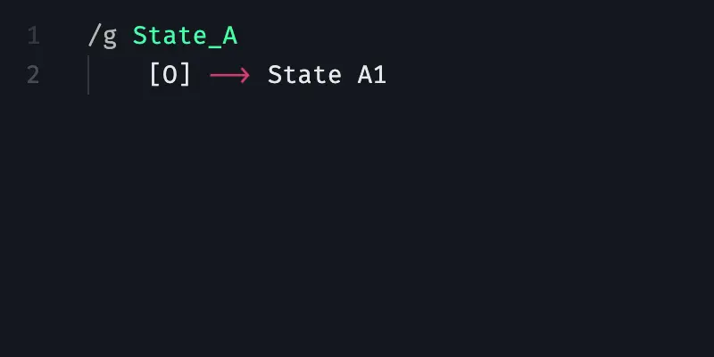
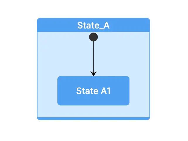
Composite State (Group)
Composite states, also known as superstates, are states that contain other states within them. These sub-states or internal states have their own lifecycle within the composite state, providing an additional level of detail and complexity in the state diagram.
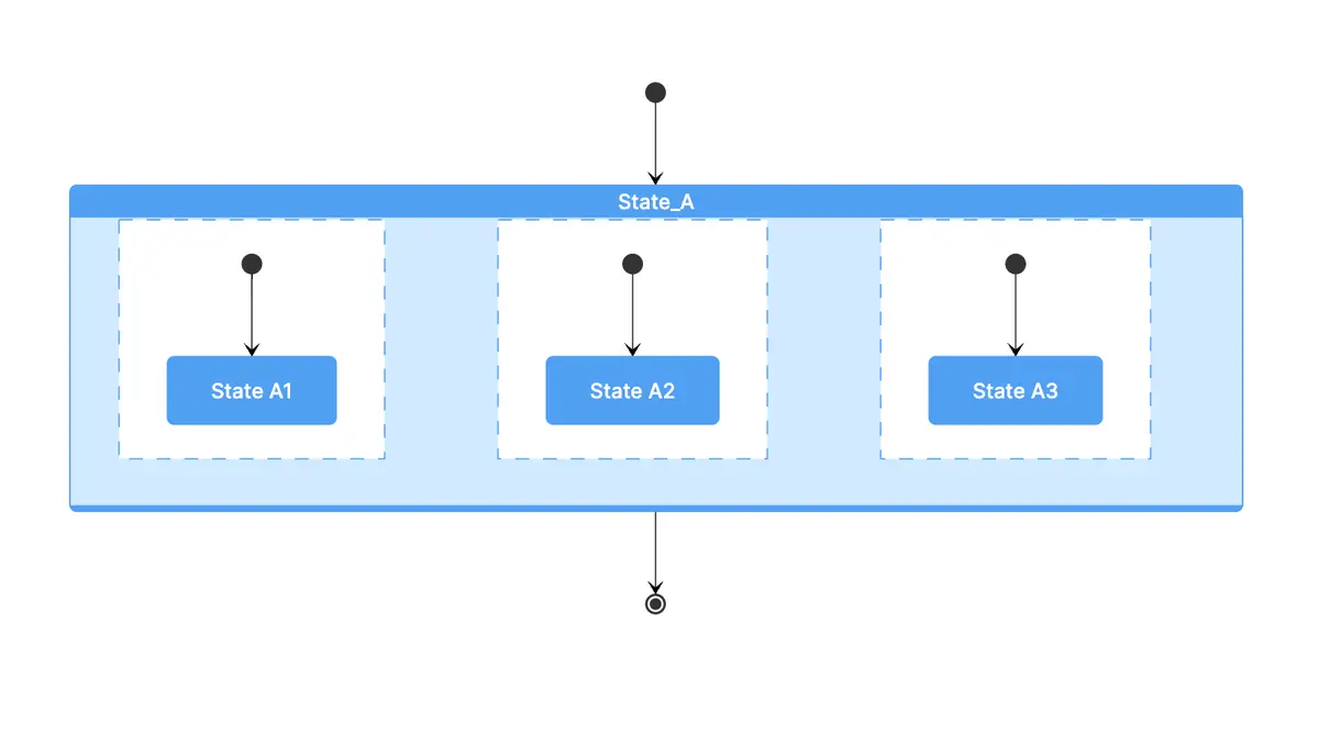
Concurrent States
Concurrent states signify situations where an object can be in more than one state simultaneously. This allows for the modeling of complex behaviors where multiple activities or processes can occur at the same time.
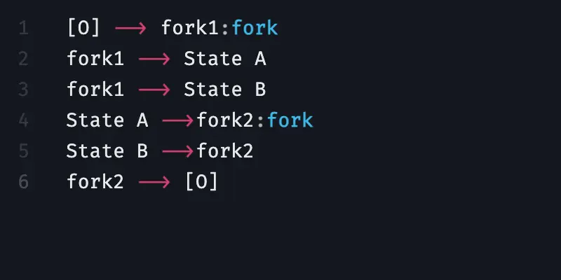
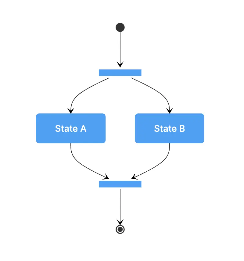
Forks and Joins
Forks and joins represent points of divergence and convergence in the flow of control. Forks split the flow into multiple concurrent paths, while joins bring these paths back together. They are crucial for modeling parallel or concurrent activities.
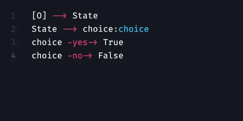
Choice
Choices, often represented by diamond shapes, symbolize decision points where the next state depends on certain conditions. They allow for branching paths based on specific criteria or conditions.
Notes
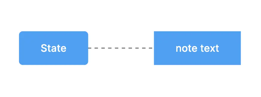
Notes, often enclosed in a rectangle with a folded corner, provide supplementary information or context about a state or transition. They can include comments, constraints, or any other relevant information for understanding the state diagram.
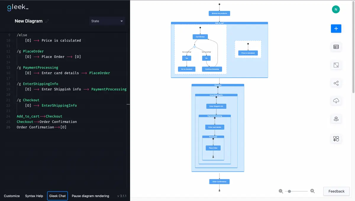
State diagram syntax in the Gleek App
Gleek has recently added support for state diagrams. Here are the syntax instructions you need to understand to create a state diagram:
State: Every state must be named. This is the basis of your diagram.

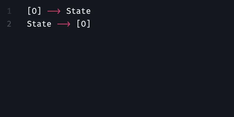
Beginning and End: Use [O] to indicate the start and finish of your diagram.
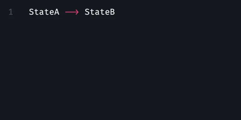
Transition (arrow): Use "-->" to add a transition between two states.
Text: Label transitions using "-text->".
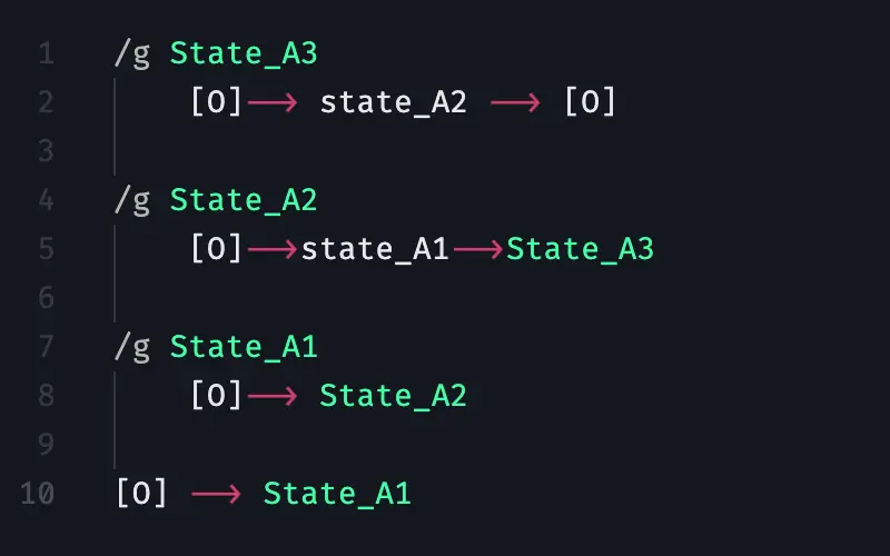
Composite State (group): Define composite states using "/g State_A". To add an internal state, press TAB and type State A1.
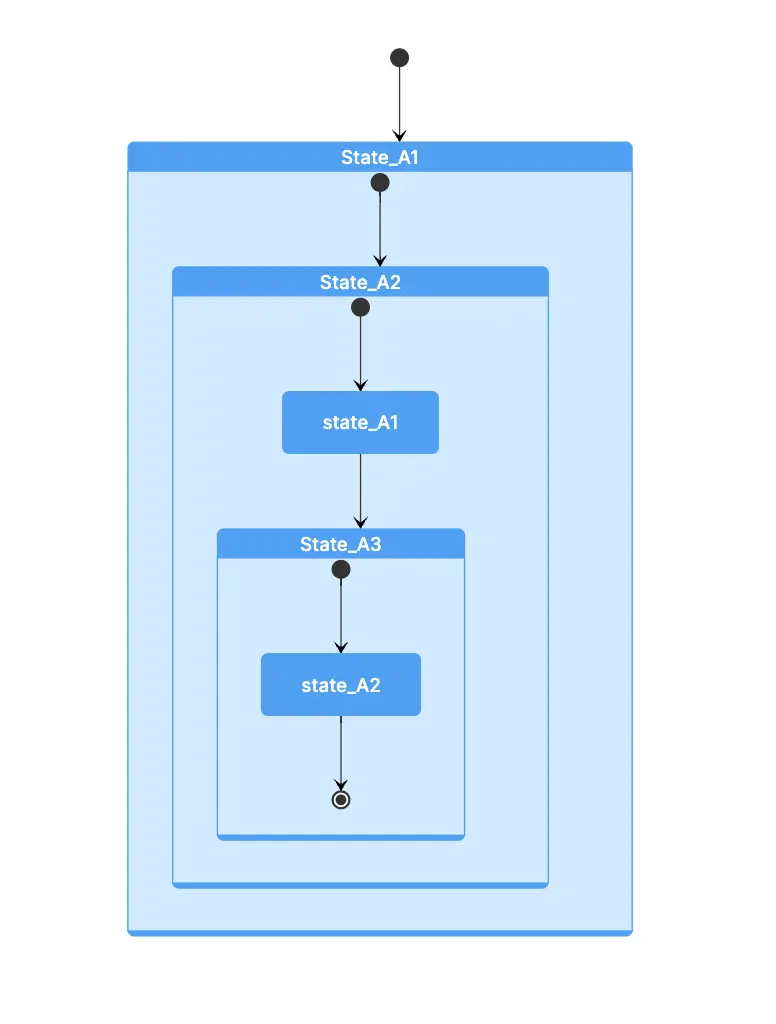
Layers in Composite State: For multiple layers within the composite state, begin with the final state (e.g., "StateA3") and progress to the encompassing state (e.g., "StateA1").
Choice: Create a choice between two options with "Name:choice". The name will not be displayed but is necessary for reference and differentiation from other choices.
Forks and Joins: Establish forks and joins with "Name:fork." The name will not be displayed but is necessary for reference and differentiation from other forks/joins.
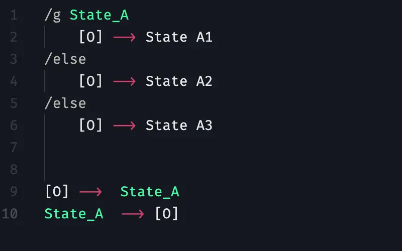
Concurrent States: Specify concurrent states by creating a group with "/g State_A", then pressing TAB and adding the states. After each state, type "/else " from a new line. Don't forget to include space after typing "/else " so the concurrent state is displayed.
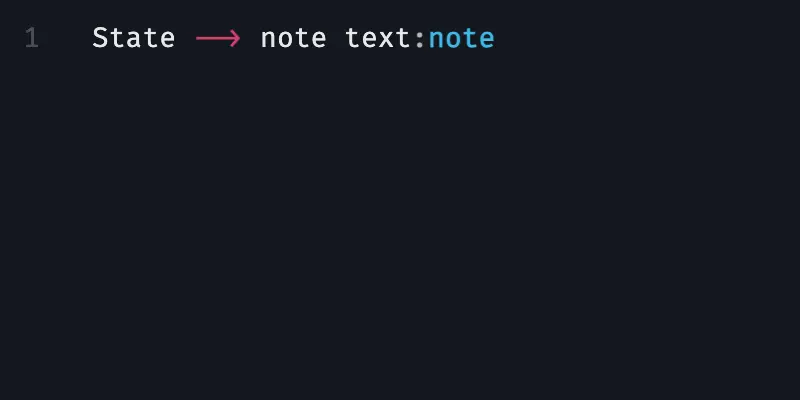
Notes: Insert state notes as "Note text:note."
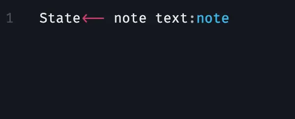
To align the note on the left side of the state, insert a left-directed arrow.

State machine diagram example: Online shopping process
In this section, we'll explore how to create a state diagram for an online shopping process. This will help you understand the practical application of the syntax instructions from the previous sections.
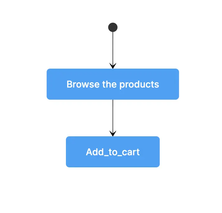
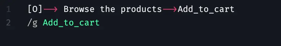
1. Browse the Products
The online shopping process begins with browsing the products. This initial state leads to "Add to Cart". In Gleek, this is represented as follows:

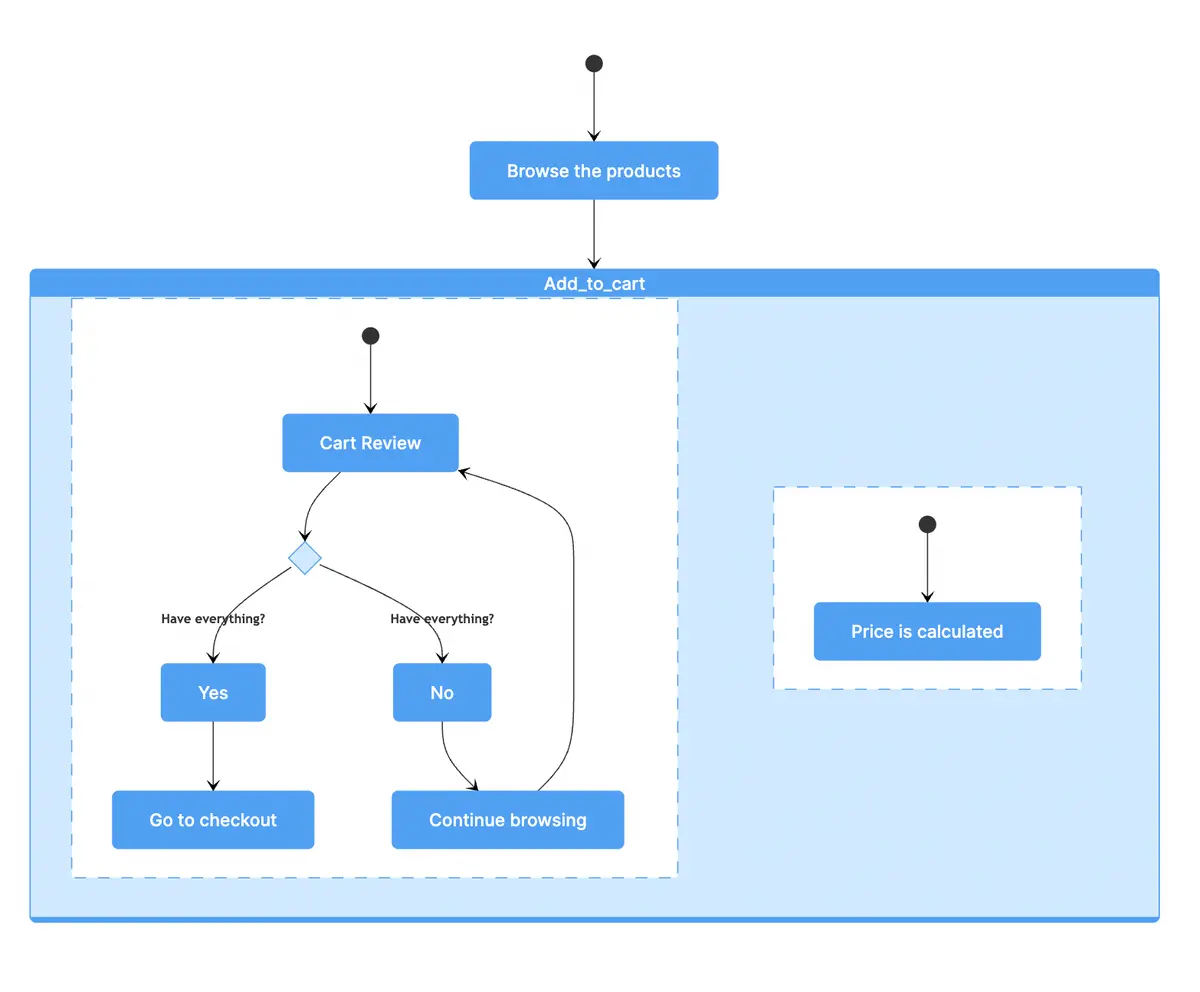
2. Add to Cart
The "Add to Cart" state is a concurrent state that includes two simultaneous sub-states happening simultaneously: "Cart Review" and "Price is Calculated." In Gleek, a concurrent state is created using "/g" followed by the name of the concurrent state. Here's how you can represent it:
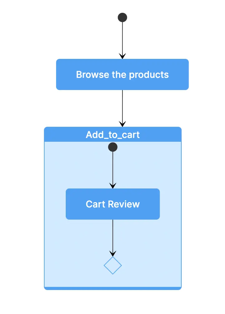
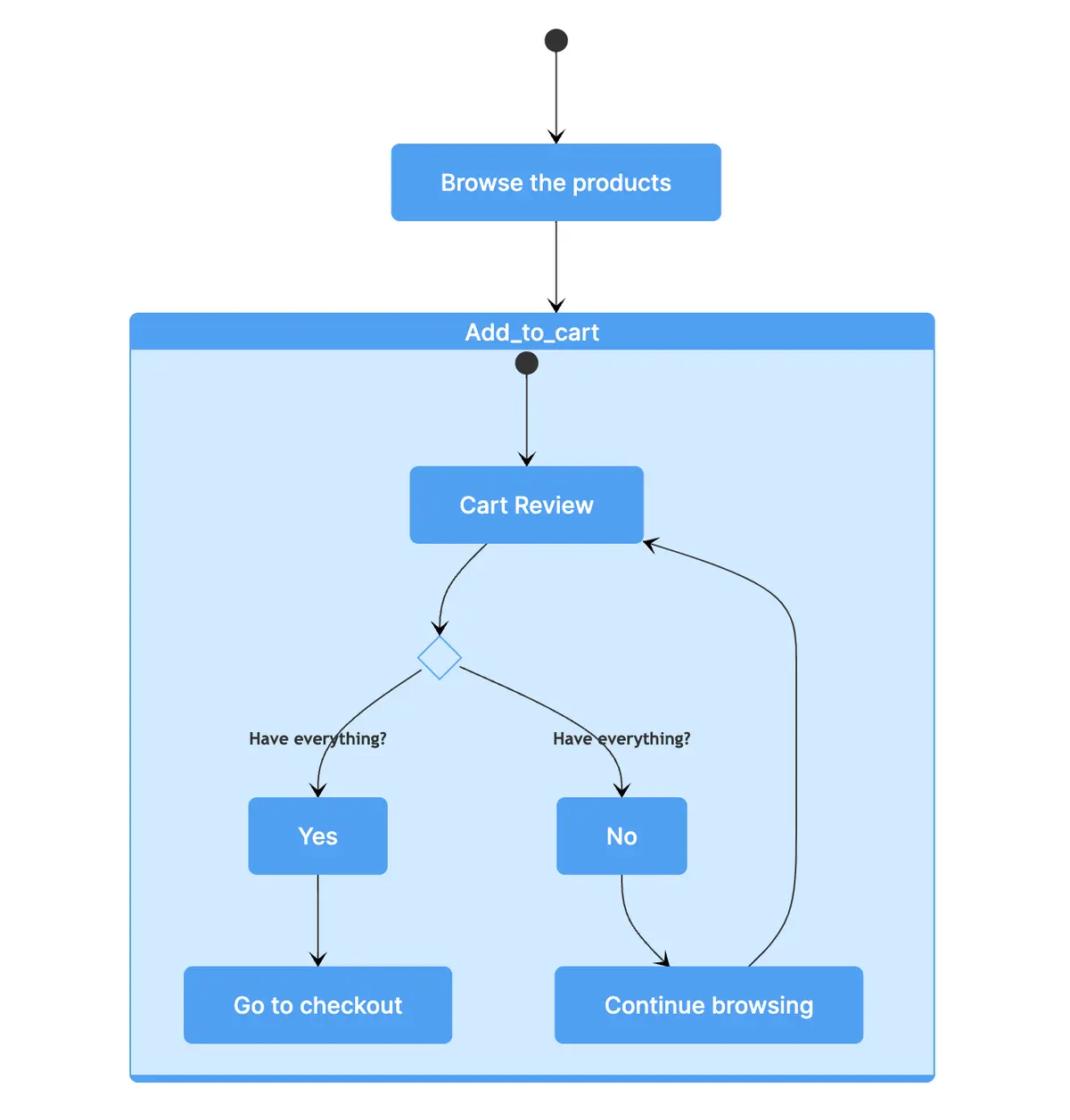
3. Cart Review
The first sub-state within "Add to Cart" is "Cart Review." We can represent this in Gleek as follows:
Next, we add a choice to "Cart Review" where the customer decides whether to purchase or continue browsing. We link "Cart Review" to a choice named "CartReview."
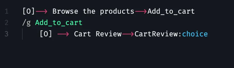
Note that the choice's name is not displayed but is necessary for reference and differentiation from other choices.
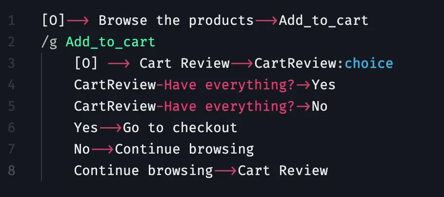
Now, let's add two scenarios to this choice: When the user has everything they need and when they don't. Each line should start by pressing the TAB button:
The second concurrent sub-state within "Add to Cart" is "Price is Calculated". To add a sub-state to a concurrent state, start with "/else" and add the sub-state.
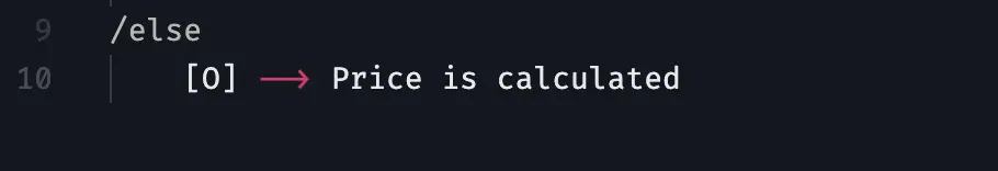
Note that it is important to add a space after "/else", otherwise the concurrency state won't be displayed.
This concludes the first part of our online shopping state diagram. In the next section, we will continue to build upon this foundation, adding more states and transitions to represent the complete online shopping process.
4. Checkout Composite State
The checkout process in an online shopping experience typically involves several steps. In Gleek, composite states are displayed from the final to the initial state.
Identify Checkout Processes
During the Checkout phase, we typically encounter three main processes:
Entering Shipping Info
Payment Processing
Placing the Order
Creating the Composite State
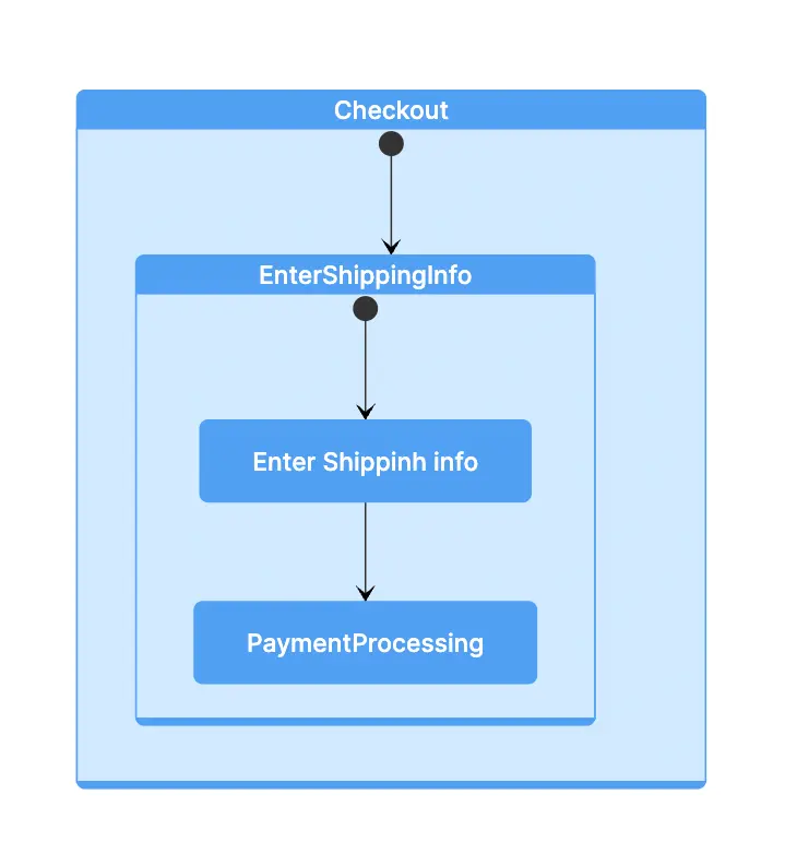
To create a composite state in Gleek, we group these processes together. We initiate the composite state using the '/g' notation and name it "Checkout."
Next, press ENTER to move to the next line, press TAB, and introduce a starting symbol that leads to the first process, "EnterShippingInfo."

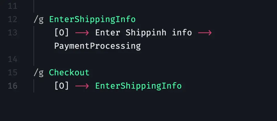
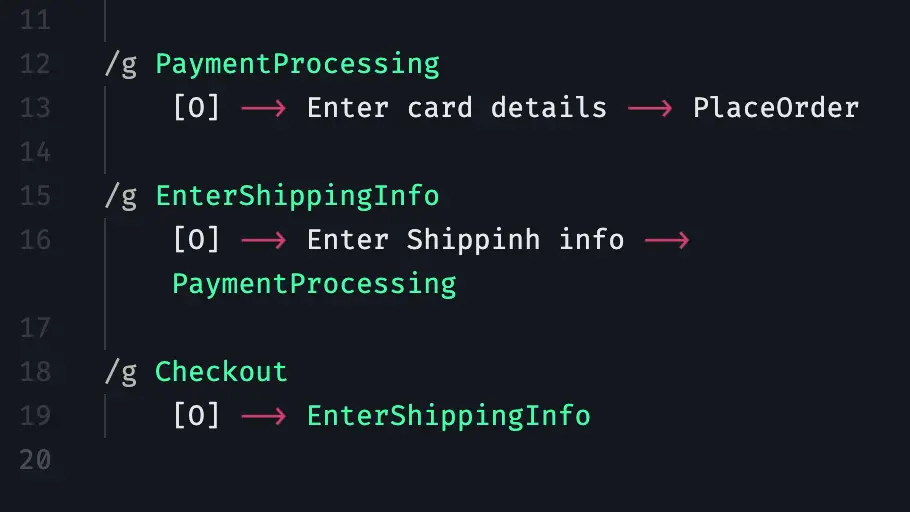
We then move to the "Enter Shipping Info" sub-state. We create a group for this process and introduce the initial symbol, label the process, and add a transition to the second process, "PaymentProcessing."
The second process, "Payment Processing," is added above the "EnterShippingInfo" sub-state. We start with an initial symbol, name the process, and establish a link to the final process.
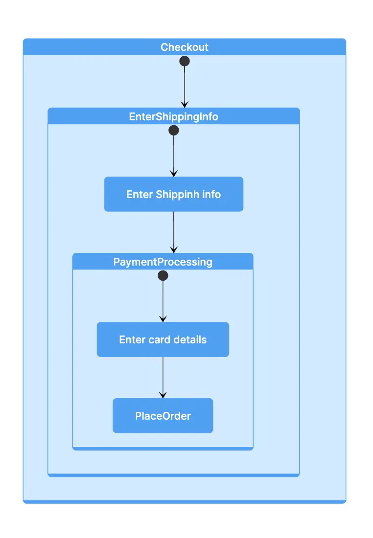
Finally, we introduce the last sub-state, "Place Order," at the very beginning of the composite state. On a new line, we insert an initial symbol connecting to "Place Order," followed by a transition indicating the end of the process.
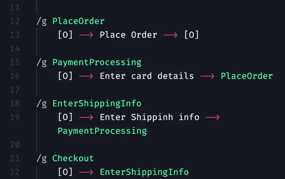
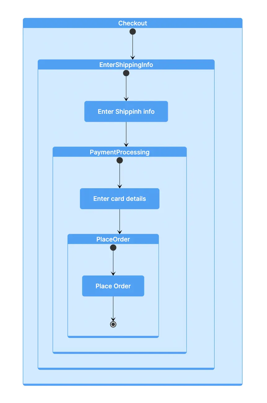
Altogether, the code for the composite state will look like:
/g PlaceOrder
[O] --> Place Order --> [O]
/g PaymentProcessing
[O] --> Enter card details --> PlaceOrder
/g EnterShippingInfo
[O] --> Enter Shipping info --> PaymentProcessing
/g Checkout
[O] --> EnterShippingInfo
5. Connect the States
Now, we add the final states to complete this state diagram. We connect the "AddToCart" state to "Checkout."
AddToCart-->Checkout
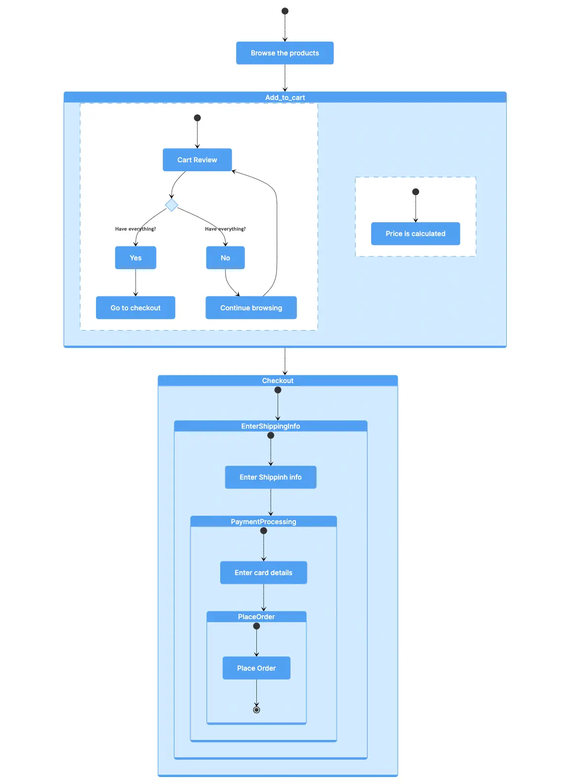
Order Confirmation
After the checkout process is complete, we transition to the "Order Confirmation" state.
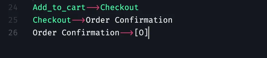
6.Finish the Diagram
We conclude the state diagram by connecting "Order Confirmation" to the final state.
This completes our online shopping state diagram.
By following these steps and understanding Gleek's syntax, you can create state diagrams for any process or system.