What is UML?
Developers often use the Unified Modelling Language (UML) when designing software. UML is not a programming language, but a visual diagramming language that uses standardized models and diagrams to represent the design of the system. It was created to help software engineers and system designers better understand each other’s needs when cooperating on developing complex systems. UML originates from the mid-1990s and has been evolving and changing ever since.
What is a sequence diagram in UML and what is its purpose?
One type of UML diagram is a sequence diagram. Both developers and users depend on these because they are a very straightforward way of modeling interactions between objects in a time sequence. A sequence diagram helps create an overview of how a system works and how all the different parts interact with each other over time, carry out the required actions, and how processes are completed. Sequence diagrams can also be called event diagrams or event scenarios. A simple example of a real-world interaction that could be represented by a sequence diagram would be a user subscribing to an email service. The diagram would show the sequence of interactions between the user and the email domain over time.
Sequence diagram notations
In order to understand what a sequence diagram depicts, we need to become familiar with its components and structure. A sequence diagram descends from top to bottom showing a sequence of interactions and consists of a number of sequence diagram notations. So let’s take a closer look at the notations used to draw a sequence diagram.
Actor (object) – this is at the top of the sequence diagram and represents an object interacting with the system. Objects, or actors, represent various roles, such as users or external systems. In our email example, this would be a user registering an email address. Note that a sequence diagram can have multiple actors.
Lifeline – this is a vertical parallel dashed line showing the object's existence in time. Multiple lifelines can never overlap. In our email example, a lifeline could show the creation of a username and password, and logging after email verification.
Activation Bar – this shows the time needed for an actor to process the task and during which the object remains active. It is represented by a long thin rectangular box on the lifeline.
Message – the interaction between the objects (actors) in a sequence diagram happens by means of the sending of messages. These messages are represented by horizontal arrows in sequential order. Message can be sent from left to right and vice versa. The arrow indicates which object is the sender or receiver of the message. There are several different types of messages:
Synchronous message – represented by an arrow with a solid arrowhead. The message is first sent to the receiver, gets processed, feedback is returned to the sender, and only then can the sender continue and send another message. In our email example, this means that the user creates an account, a request for verification is sent to the email server, and then the user needs to wait for a verification email before logging in.
Asynchronous message – represented by an open arrowhead. This is the opposite of a synchronous message, in that the sender (message caller) does not wait for the receiver to process the message and continues its interaction immediately.
Return message (reply message) – represented by a dashed line with an open arrowhead – the message is sent back by the receiver to the sender. This can be skipped in a sequence diagram, as a synchronous message already contains a return message.
Participant creation message (create message) – sending a message can result in the creation of a new object in the sequence diagram. A create message is indicated by the word “create” over the arrow line and ends with a rectangle representing the newly created object. For example, when a user sends an online banking payment, this creates a new object in the system.
Participant destruction message (delete message) – this is the opposite of the create message notation. If a call message requires the destruction of an existing object, a delete message can be used in the sequence diagram. This is shown by an arrow line marked “destroy” and ending with a crossed-out “X” at the end.
Reflexive message (self-message) – the caller sends a message to itself. This is represented by an arrow that starts and finishes at the same lifeline for the object.
Found message – a message sent from an unknown source outside the sequence diagram. This is depicted by an arrow from a filled-in circle to the lifeline.
Lost Message – unlike a found message, this is sent to an unknown recipient outside the diagram and is shown by an arrow from a filled-in circle to the lifeline.
Comment – if you need to add a description to explain a particular process, you can use a comment, or note. Notes are shown as a rectangle with a folded-over corner and can be connected to an object with a dashed line.
How are sequence fragments used in complex interactions?
Sequence fragments help to deal with complex interactions between multiple objects over time. They enable you to frame part of an interaction. A fragment is defined by an interaction operand with guard values. In a sequence diagram, a fragment is shown by a rectangular with an operator in the top left corner.
The most common operators used are:
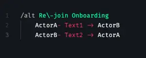
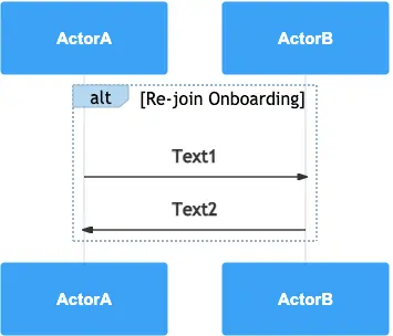
Alternatives (alt/else) – an operator with a choice of two or multiple operands when only one gets selected. If a guard is found, then a value is selected; if none is met, an operand with else value is chosen. In order to display the alternatives in the sequence diagram, a fragment box is divided by a dashed line into smaller boxes.
Options (opt) – similar to alternatives, this represents a choice, but only between two operands. The condition is either met or not met. This is also depicted by a box with an operand in the top left corner, but it is not divided by a dashed line like alternatives.
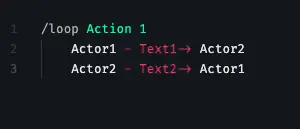
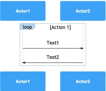
Loops (iterations) – the fragment can be executed multiple times until the condition is met. The loop can have Boolean values such as true or false or a lower and upper number of interactions – minimum and maximum interactions. These values are written in brackets after the loop operand in the top left corner.
Parallel (par) fragments run parallel in the lifeline and their order is not important.
How to create sequence diagrams in Gleek - the pro cheat sheet
You can create powerful sequence diagrams using our unique Gleek syntax. To get you going, here’s a detailed explanation of how to use the right syntax for the right notation.
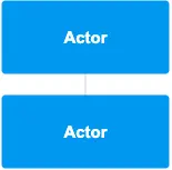
Let’s start by creating an actor. You can do that by just writing its name. Use any name you like and a box will be drawn to represent the actor.
Here’s how it will look in the syntax:

And here’s how it will be drawn in the diagram:
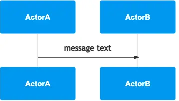
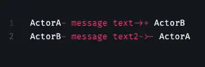
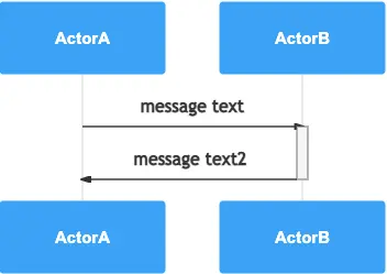
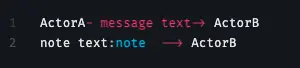
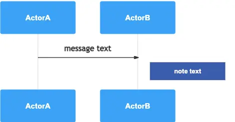
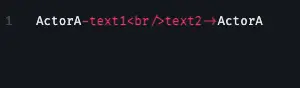
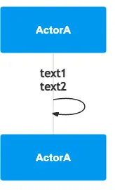
You can draw a solid line with an arrowhead by using "-message text->" to depict a message between actors or to create a self-message (reflexive message).
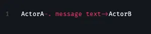
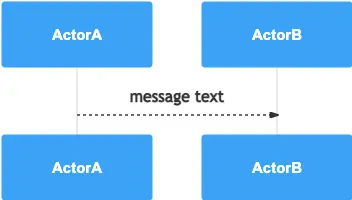
Instead of a solid line, you can create a dotted line with an arrowhead with "-. message text->" to depict a message between actors or a self-message.

You can display an activation bar by adding "+" and deactivate an activation bar by adding "-"
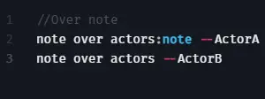
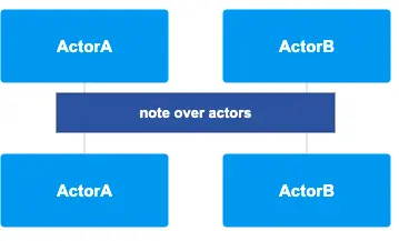
Add a note over multiple actors by simply creating connections to these actors, e.g. “note over actors:note -- ActorA” and “note over actors -- ActorB”
Add a note on the left-hand side of the actor’s lifeline using ":note <-- Actor". Add a note on the right-hand side using ":note --> Actor"
Create a multiple-line message using <br/>
Create a loop operator using "/loop". Create other operators, such as alternative, parallel, and option by using "/alt", "/par", "/opt"
Else (/else) is available for alternative and parallel operators.
Add s nested sequence diagram within operators by using the TAB button.
Add a dash in an operator’s name by using "\-"e.g. /alt Re\-join Onboarding
Use two slashes "//" to create a comment.

While a single slash "/" opens the handy Gleek template gallery ;)
That should be enough to get you started with creating complete and detailed sequence diagrams in Gleek! Remember that you can always right-click in the code area to display additional options, including shortcuts.