
What are class diagram relationships?
UML class diagrams allow developers to graphically represent a system or program. UML stands for unified modeling language. UML diagrams map out the classes, attributes, operations, and relationships among objects in a system. Developers use UML class diagrams to view the structure of static systems.
What are UML classes exactly? UML classes represent objects that have a common structure and behave in a similar way. In UML classes appear in a rectangle with attributes and operations listed below. We connect classes with arrows that show relationships between them.
So, what exactly are class diagram relationships? UML class diagram relationships show how one class affects another. Sometimes one class acts as a parent to another. Other times the one class might inherit the function of another class. Some of these relationships are stronger than others. We can show all of this information in UML class diagrams by using class diagram arrows.
Make your own UML class diagram with Gleek.
What, exactly is the purpose of class diagram arrows? Developers use class diagrams to show different objects in a system. The UML class diagram maps out the object’s attributes, operations, and how they relate. The arrows that connect classes show important relationships. The arrows denote association, inheritance, aggregation, composition, dependency, and realization among others. Let’s take a closer look at the arrows and how they function in UML class diagrams.
Association
Association is the most basic of relationships. Association means any type of relationship or connection between classes. For example, we show a direct link between a city bus and its riders using an association line. We show a simple association with a straight line. In gleek.io we create this by typing two hyphens: —

There are several sub-types of association.
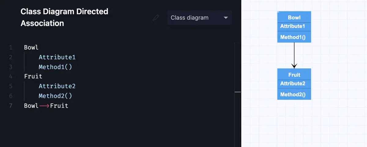
Directed association
Directed association shows a strong relationship between classes. The classes must communicate. We represent a direct association with an arrow pointing to our object class. For example, a bowl might contain fruit. The bowl acts as a container class for the fruit class. In gleek.io we create this association with two hyphens and a greater-than symbol. The syntax looks like this: –>
Make your own UML class diagram with Gleek.
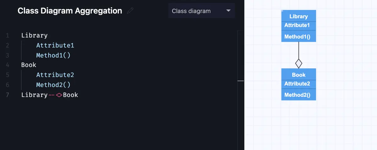
Aggregation
We use aggregation arrows when we want to convey that two classes are associated, but not as close as in direct association. The child class can exist independent of the parent element. For example, a book still exists if somebody checks it out from the library. In gleek.io we create aggregation arrows by typing two hyphens followed by a lesser-than symbol followed by a greater-than symbol. The syntax looks like this: –<>
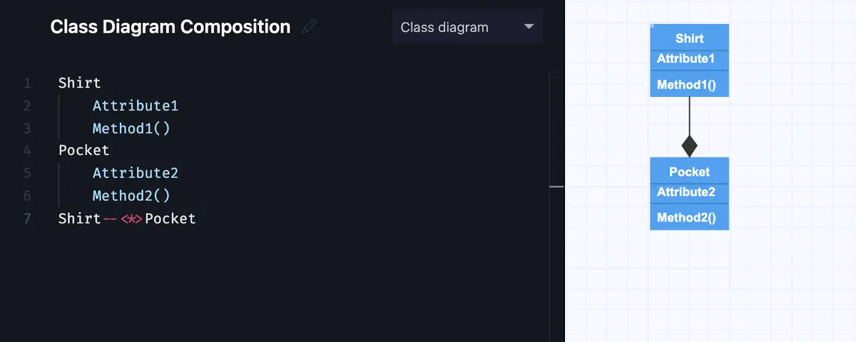
Composition
Composition arrows show up in UML class diagrams when we want to show a similar association to aggregation, with a key difference. Composition associations show relationships where the sub-object exists only as long as the container class exists. The classes have a common lifecycle. For example, a pocket on the front of a shirt cannot exist if we destroy the shirt. In gleek.io we create a composition arrow by typing two hyphens followed by a star inside a lesser-than and greater-than symbol. The syntax looks like this: –<*>
Read a comprehensive comparison of Aggregation and Composition relationships.
Make your own UML class diagram with Gleek.
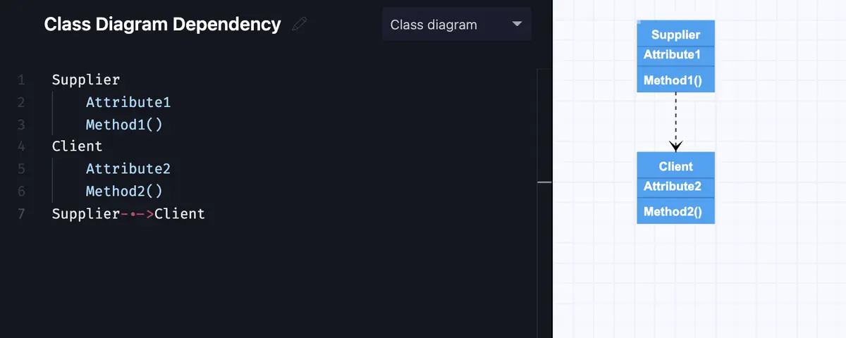
Dependency
Dependency arrows show us where two elements depend on each other, but in a less strong relationship than a basic association. Changes to the parent class will also affect the child class. Dependency shows a supplier-client type of relationship. In gleek.io we create a dependency arrow with a hyphen, a period followed by another hyphen, and a greater-than symbol. Our syntax will look like this: -.->
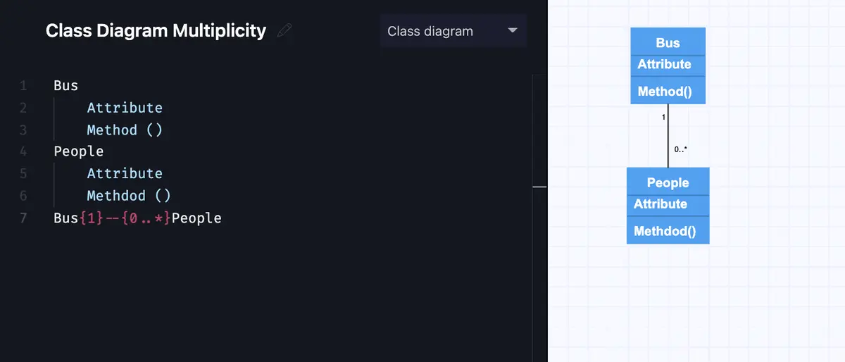
Multiplicity
Multiplicity or cardinality arrows show a place in our UML diagram where a class might contain many (or none!) items. For example, a city bus might have any number of riders at a given time. People constantly get on and off as the bus moves through the streets. We show this in our diagram with the notation 0..* meaning our class might contain zero to many objects. In gleek.io we create multiplicity with numbers inside curly brackets with two hyphens in the middle. Our syntax looks like this: {1}–{0..*}
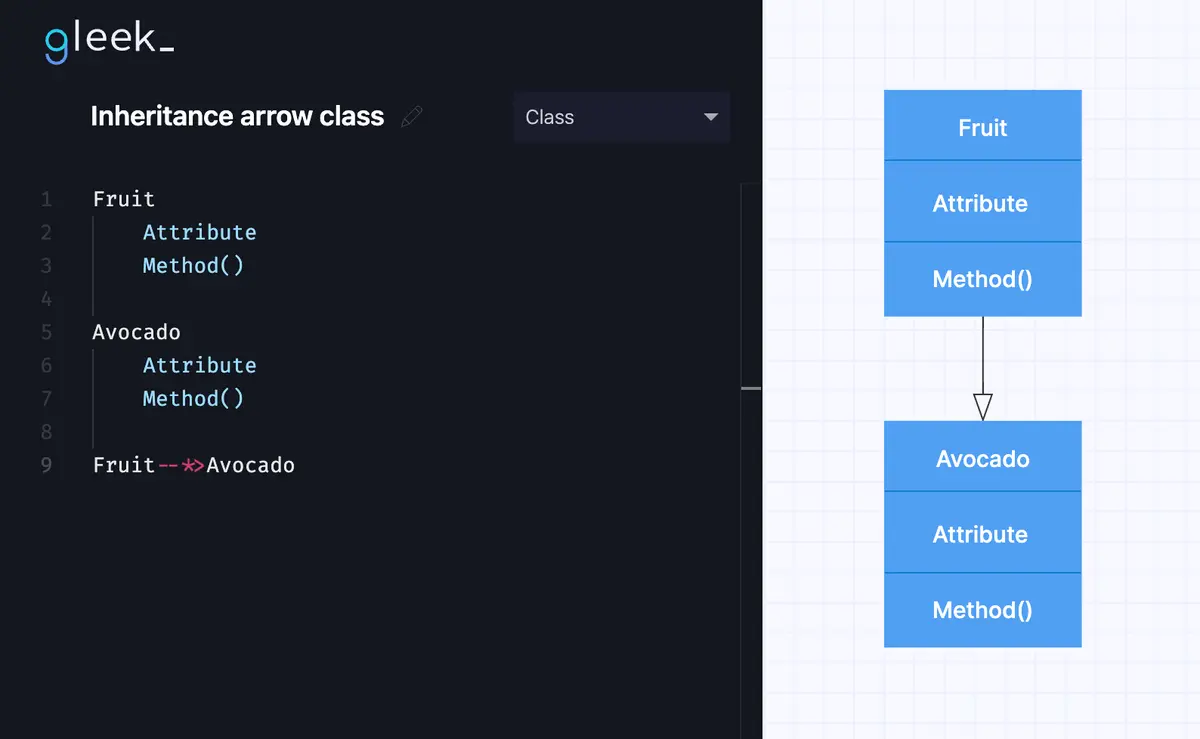
Inheritance
We use Inheritance arrows to show a child class inherits functionality from the parent class. For example, an avocado is a type of fruit. Fruit is the super-class. Avocado is the sub-class. The avocado inherits its fruitiness from its fruit parent. To show inheritance in our UML class diagram in gleek.io, we type two hyphens followed by a star and a greater-than symbol. Our syntax will look like this: --*>
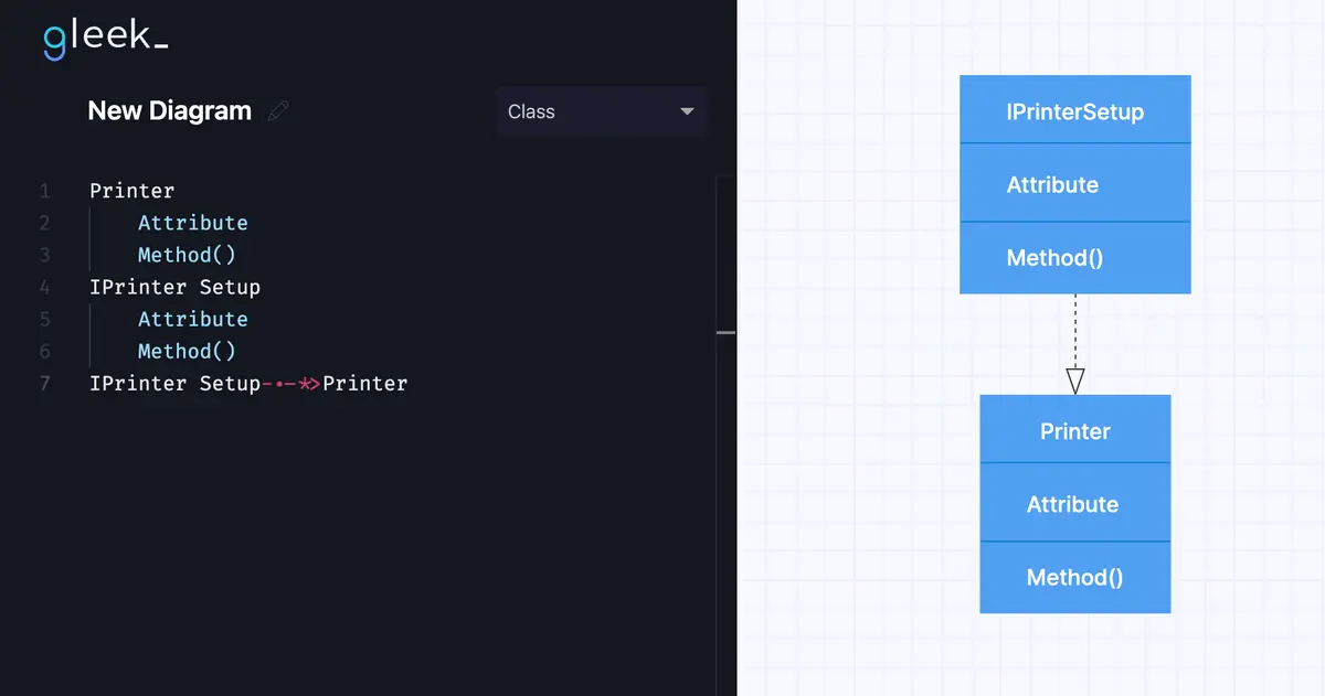
Realization/Implementation
We use realization or implementation arrows to indicate a place where one class implements the function defined in another class. For example, the printer setup interface sets the printing preferences that are being implemented by the printer. The arrangement shows a realization association. To show the relation in gleek.io, we type a hyphen, a period followed by another hyphen, a star symbol, and a greater-than symbol. Our syntax will look like this: -.-*>
Make your own UML class diagram with Gleek.
As you see, association arrows in UML class diagrams give software development teams a flexible means of describing relationships between classes. Using gleek.io developers quickly map out systems using easy-to-understand syntax, without the need to drag-and-drop. Gleek gives developers a powerful tool to create not only UML diagrams but also flowcharts, entity-relationship diagrams, and much more. Give gleek.io a spin and leave cumbersome mouse-clicking behind.
Related posts
UML Class diagram for online shopping: Step-by-step tutorial
How do we create a Class diagram for a Library Management system?
UML relationships explained: Dependency, Realization, Association
Hospital management system class diagram using Gleek App
UML diagram types: everything you need to know