
What is a relational schema?
A relational schema is a blueprint used in database design to represent the data to be entered into the database and describe how that data is structured in tables (called relations in relational schemas). The schema describes how those tables relate to each other.
In the relational schema, the table, or relation, consists of a set of named, but unsorted, columns (called attributes in relational schemas) and an undefined number of unnamed and unsorted rows (called tuples in relational schemas). Each row is unique, but the rows can be moved around as needed and stored in any order, modified, or deleted without impacting the efficient operation of the database.
Make your own ER diagram in Gleek.
How do you convert an entity-relationship diagram to a relational schema?
While you might start by designing your database using an entity-relationship (ER) diagram, once it’s time to build it, you need to convert that conceptual model into a logical model that breaks down entities, attributes, and relationships into tables, columns, fields, and keys.
Find out more on how ER diagram differs from Relational schema.
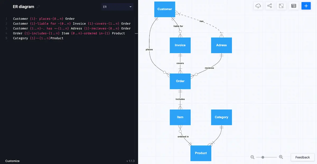
Check out our latest tutorial on an ERD for an E-commerce website using AI chat.
How to convert strong entity types
The most straightforward way to convert strong entity types is to create a relation, or table, for each. The first step is to identify the primary key, the attribute that will become the differentiating column in the relation. This will be the column in the table that has a unique value for every row in the table.
The primary key will be underlined in the box that represents the table in the relational schema.
If you’re creating a table of products, the primary might be the product number assigned to it in your system. For a relation containing students in a university, student ID will probably be the best choice. Or employee ID for a table of employees.
This primary key is a unique value that will not be repeated in any other row of that particular relation. It is also very unlikely to change. Once you’ve identified the primary key, you can go on to translate the other attributes into the columns of the table. For items of clothing in a product database, these columns might include price, color, size, and material. For students, the columns might include first name, last name, date of birth, address, phone number, and email address.
How to convert weak entity types
Converting weak entity types is almost the same process, in that they get their own table, but the difference is that the primary key of the strong entity type takes on the role of a foreign key in the weak entity table. While a primary key can exist without reference to any other table, the foreign key will always reference a primary key in another table. For instance, student IDs might be stored in a department table as foreign keys.
Make your own ER diagram in Gleek.
Foreign keys in a table are indicated by drawing a line to the corresponding primary key in the table from which it originates – you can also add “(FK)” to the key to further highlight that it is a foreign key.
Converting relationships
So you’ve converted the entities in your ER diagram to tables, with attributes represented as columns. Now it’s time to convert the relationships.
In database design, you need to be aware of several terms that describe relationships. We’ll start with a degree. This tells you how many entity types can take part in the relationship. Three different degrees are possible – binary, unary, and ternary.
A binary relationship describes two different entity types participating. For instance, you might have a student enrolled in a course. The student and the course are both entity types.
A unary relationship describes when the same entity type is the only participant. For example, you could have a citizen table in a government database that records when one citizen is married to another. The entity types are the same in this case, so it is a unary relationship.
A ternary relationship describes when there are three different entity types participating in the relationship. For instance, an online store might have tables representing customer, product, and supplier. The relationship between these three could, depending on how the system is designed, be a ternary relationship.
Alongside degree is cardinality. This should be no problem to you if you’re already familiar with entity-relationship diagrams (don’t forget that you can read our article to refresh your memory). Cardinality simply tells you the numerical relationship between entity types. Again, we have three possible cardinalities: 1:1, 1:N, and M:N, or one-to-one, one-to-many, and many-to-many.
These pieces of information for each relationship should tell you what you need to know to design the tables, or relations, in your database. Combined, they tell you when you need to create a new table and what foreign keys have to be included in that table.
Finally, you also need to be aware of participation constraint, which tells you whether the existence of an entity type depends on it being related to another entity type. You can have total or partial participation. An example of total participation might be a driver’s license. A driver’s license always applies to one person, so there is total participation on the part of the driver’s license entity type.
Representing relationships in a relational schema
Once you’ve identified the degree and cardinality of the relationships in your ER diagram, you can start to transform them into relations. This is where your primary and foreign keys will come into play.
Binary 1:1
This can be illustrated with our driver’s license example from above. In this case, the driver is a partial participant, while the driver’s license is a total participant. The tables created can be related to each other by using the primary key of the driver as a foreign key for the driver’s license. Alternatively, you could use the primary key of the license as a foreign key in the driver’s table. Or you could do both.
Binary 1:N
In this case, you can imagine a university in which a teacher can teach several different subjects. The primary key of the teacher would be used as a foreign key for each subject.
Binary M:N
For this relationship, you can again return to the university example. Maybe each subject can be taught by many teachers. In this case, a new relation is created in which the primary key is a composite of two foreign keys from the subjects and teachers.
Unary 1:1
As in a binary 1:1 relation, you have three options for unary 1:1. Primary key of A as foreign key for B, primary key of B as foreign key for A, or both.
Unary 1:N
For unary 1:N, you can use a recursive foreign key. The foreign key will reference a primary key in the same relation.
Unary 1:M
Here, you need to create a new relation. The primary key of the new table is composed of two attributes that take their values from the same primary key.
Ternary relations
Ternary tables require a third table to describe the relational schema. To return to our e-shop example above, we have three entities in a relationship: customer, product, and supplier. To describe how a customer orders a product from a particular supplier, you need to create a new table called order. The primary key of the new table takes foreign keys from each of the other participants so that the order relation correctly describes the relationship.
Make your own ER diagram in Gleek.
Going from an ERD to a relational schema can take time and needs to be done carefully, but if you’ve done a good job on your original entity-relationship diagram, you should be starting off from a position of strength. You might call us biased, but we recommend you try Gleek for all your diagramming needs 😉
Related posts
ER diagram for an E-commerce website with Gleek's AI chat
Guide to entity-relationship diagram notations & symbols
ER diagram example: online shopping system (Crow’s Foot notation)
What is the entity-relationship diagram in database design?
Crow’s foot notation in entity-relationship diagrams
Crow’s Foot vs. Chen notation: detailed comparison for 2022
Enhanced entity-relationship diagram: features and components
Relational schema vs. ER diagrams: A detailed comparison
The logical data model explained
Composite and other attributes in the entity-relationship model
What is data modeling? Types & process