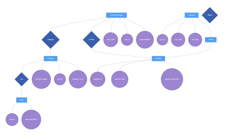
This entity-relationship diagram maps out an inventory management system. Each inventory manager controls payments and manages inventory with attributes like User Name, User ID, and Responsibilities. Each inventory item has attributes like Quality, Item ID, and Inventory ID. When a customer (with ID, Name, Email attributes) places an order, the system processes the payment.
Edit this diagram in Gleek
Inventory management diagram code in Gleek
User -Insert card-> ATM
ATM -Card number->+ Database
Database -Card ok->- ATM
ATM -Pin request->+ User
User -Pin->- ATM
ATM -Check pin->+ Database
Database -Pin is correct->- ATM
ATM -Option menu->+ User
User -Withdraw request-> ATM
ATM -Amount request-> User
User -Amount selected->- ATM
ATM -Check the funds-> Database
/alt Transaction approved
Database -. Suffcient funds-> ATM
ATM -Dispense cash-> User
User -Take cash-> ATM
ATM -Return card-> User
/alt Transaction rejected
Database -Insufficient funds-> ATM
ATM -Show rejection details-> User
ATM -Return the card-> User
About ER diagrams
We often make an entity-relationship (ER) diagram, ERD, or entity-relationship model, in the early stages of designing a database. An ERD is perfect for quickly sketching out the elements needed in the system. The ERD explains how the elements interact. ER diagrams can be shared with colleagues. Their simplicity makes them ideal even for non-technical stakeholders.
Similar ER diagram examples
Simple ER diagram example with Chen notation
Online shopping entity-relationship diagram
Banking system entity-relationship diagram
Inventory management system ER diagram
Library management system ER diagram
Travel management system Er diagram
College management system ER diagram