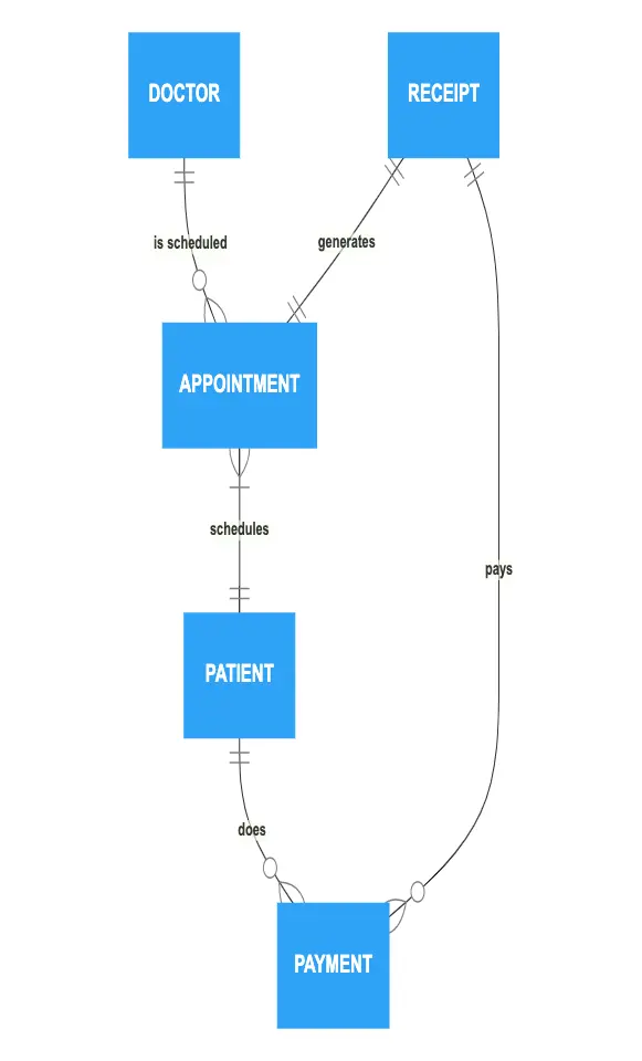
This ER diagram represents a hospital management system. A patient can schedule one or many appointments when a doctor can have none or many appointments available. The system schedules an appointment with exactly one doctor. The system applies one payment to exactly one patient and one patient can make several payments. The patient pays their receipt with none or several payments. One paid receipt can generate one appointment.

Edit this diagram in Gleek
Hospital management system diagram code in Gleek
DOCTOR
APPOINTMENT
PAYMENT
PATIENT
RECEIPT
DOCTOR ||-is scheduled-o> APPOINTMENT
APPOINTMENT <|-schedules-|| PATIENT
PATIENT ||-does-o> PAYMENT
RECEIPT ||-pays-o> PAYMENT
RECEIPT ||-generates-|| APPOINTMENT
About ER diagrams
We often make an entity-relationship (ER) diagram, ERD, or entity-relationship model, in the early stages of designing a database. An ERD is perfect for quickly sketching out the elements needed in the system. The ERD explains how the elements interact. ER diagrams can be shared with colleagues. Their simplicity makes them ideal even for non-technical stakeholders.
Similar ER diagram examples
Simple ER diagram example with Chen notation
Online doctor appointment system ER diagram
Banking system entity-relationship diagram
Travel management system Er diagram
College management system ER diagram
Simple order process entity-relationship diagram
Inventory management system ER diagram