
What is the purpose of a logical data model?
The first stage in designing a database is the conceptual model and the last is the physical model, In between sits the logical model. In a logical data model, the database designer or database architect moves on from the big picture of the conceptual model and starts to look at the detailed structure of the database, adding attributes and relationships. The logical model still uses easy-to-understand business names rather than technical terms, and the designer still doesn’t commit to any specific database management system or technology. Some experienced designers even skip straight ahead to creating logical data models, although the conceptual model phase has its advantages and it’s worth considering starting at this stage.
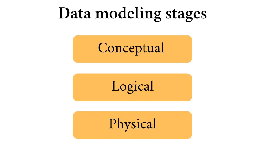
Data modeling stages
Like the conceptual model, the logical data model serves as a valuable blueprint both for designing the system and for later reference. It also provides a solid foundation for creating the actual database. Both of the first two phases of data modeling give the database designer the chance to gather the business requirements of the project. The logical data model is still focused on these requirements, so it allows the designer to make sure that the database will efficiently serve these business needs. And because it isn’t tied to any particular database system or technology, the designer retains the freedom to choose the most suitable solution at the physical data model stage.
Read how to create an effective database design.
If a designer chooses to skip the logical data model, the danger is that technology takes center stage and the business requirements could lose out to technical concerns or trends. Making changes to the database at a later stage might also be more complicated, as there is the risk that the database design will be overdependent on the database management system (DBMS). The valuable opportunity for data normalization, including the reduction of data redundancy and inefficiency, might also be lost.
Make your own ER diagram in Gleek.
As a logical data model can also be readily understood by non-technical stakeholders, their feedback and input can help make sure that their needs are being met. The logical data model also has long-term value as documentation for later stages in the development process and beyond. With a solid logical data model, it can be easier and faster to make changes or correct errors. A logical data model can also be used for impact analysis to determine the effect of changes in business requirements, rules, entities, attributes, or relationships.
What are the components of logical data models?
Logical data models consist of entities, their attributes, and the relationships between these entities. An entity is anything that needs to be stored as a data object because it is relevant to the business needs of the system. Attributes are the characteristics that describe each entity. Relationships are the associations and connections between entities.
These components can quickly and efficiently be represented in an entity-relationship diagram. ER diagrams can be used in both the conceptual and logical data modeling stages and are perfect for the rapid sketching out of a design and communicating the flow and structure of data to colleagues.
Logical data models can also be used to expand upon the attributes of each entity, by adding details about whether the attribute is a number, or integer, or a series of alphanumeric characters, or a string. The relationships between entities in the model can also be clarified more than in the conceptual data model, with a system such as Crow’s Foot notation still used throughout all three stages to explain cardinality and the nature of the relationship.
Examples of logical data models
Let’s look at a couple of examples of logical data models. A real model would be much more complicated, but we’ll keep things simple so that we can show you the basics.
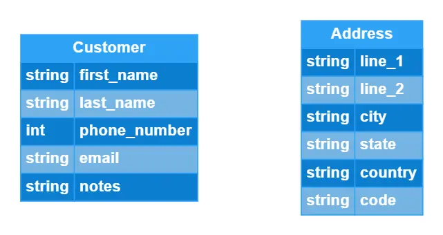
First, we can create a straightforward model that shows customer address entities. In this model, a customer has a first and last name, email address, and a field for sales team notes, all of which are strings. Each customer also has a phone number, which is an integer.
Each customer data object is also associated with zero or more addresses. If this is an online store, a customer needs to be able to create an account and then add an address, or delete an old address and add a new one. If a customer without an address tries to submit an order, they will be asked to add their shipping details.
The address consists of all strings, because the system might need to accommodate countries with postal codes that include letters as well as numbers.
Here are the entities from our example, as created in the handy Gleek diagramming tool.
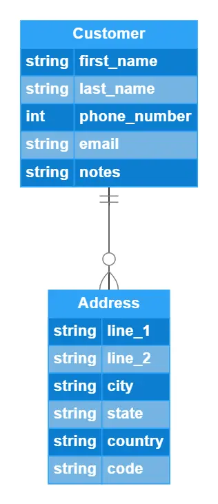
Now our logical data model needs to show the relationship between the customer and an address. Our system wants to enable each customer to have more than one address. This can be useful if they want to have orders sent to their office, or if they want to delete an old address and add a new one later.
We’ll use Crow’s Foot notation (or you can decide between Crow’s Foot and Chen notation) for this. The lines below show that each customer can have zero or many addresses, while each address data object must be associated with one and only one customer. Even if two customers share exactly the same address, which might be possible in some parts of the world, we can use unique IDs to differentiate the data objects in the system.
This is our example with the cardinality of the relationship explained.
Now let’s try a different example, for a medical clinic. The first two entities we need are patient and doctor.
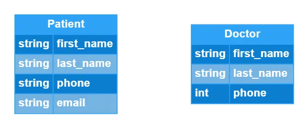
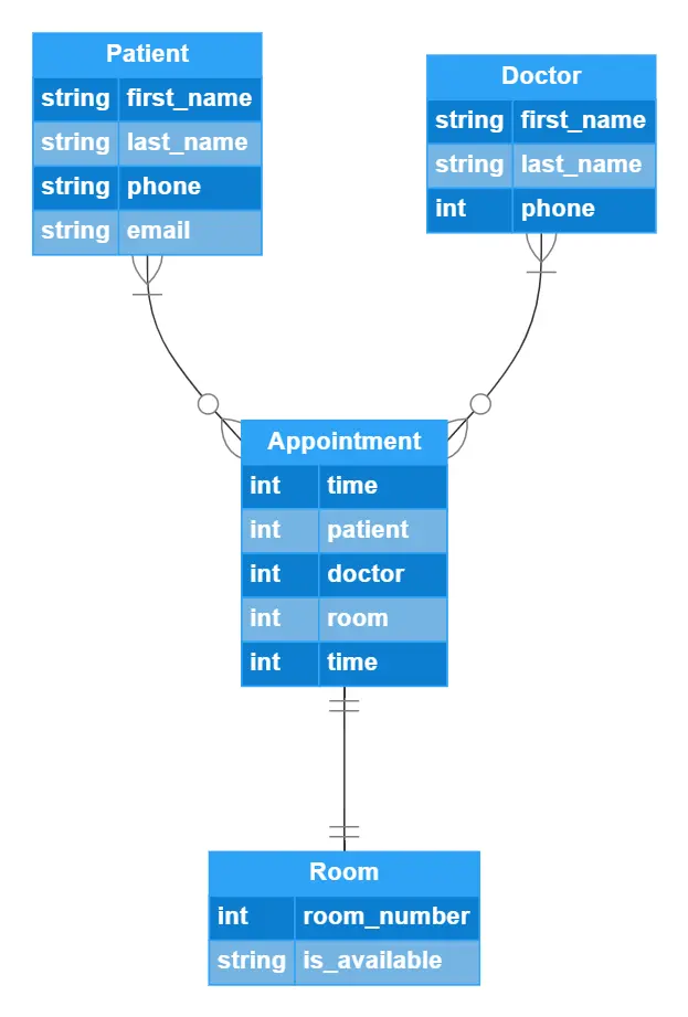
But we also want to model appointments and in which exam room the appointment will take place. The room needs at least a number and a way to indicate whether it is available. This can be a Boolean true or false string. The appointment needs to be associated with all three other entities and it also needs a time. Here are all four data objects.
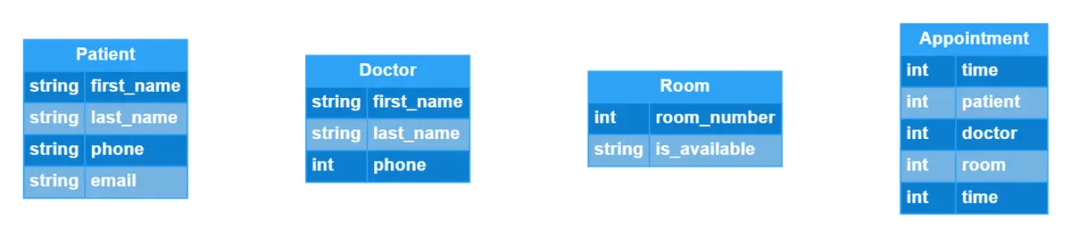
We’ll add the relationships now. Both patients and doctors can have zero or many appointments listed in the calendar. An appointment can only be associated with one and only one room.
Make your own ER diagram in Gleek.
This basic logical data model tells us a lot about how the database will ultimately need to be structured, and should help a designer to avoid making mistakes when creating the physical data model. If you would like to see how a database design might develop, you can check out a more detailed version of our clinic appointment system in our quick guide to physical data modeling. That will show you how IDs, primary and foreign keys can be added, and how even the length of the values will need to be shown. All of these details make it easier for the database administrator to choose the best DBMS and move on to creating the actual database.
Related posts
What is the entity-relationship diagram in database design?
How do you convert an ER diagram into a relational schema?
What is data modeling? Types & process
Quick guide to physical data modeling