What is a class diagram used for?
Class diagrams are used in software engineering to describe the structure of a system. A class diagram uses Unified Modeling Language (UML) to show the classes, attributes, methods (or operations), and their relationships to each other, in the system. Essential to object-oriented modeling, a class diagram can be used to model the data structure or to design the system in detail.
In a class diagram, a class is any group of objects in the system that share similar roles. These classes have relationships to each other. The class can be considered a blueprint for objects, as they are used to define objects in the system and determine what they can do and how they are created.
For a developer, a class diagram provides the opportunity to sketch out the static view of an application or system before any coding begins. This can be vital for communicating requirements to stakeholders and for optimizing development or even maintenance at later stages in the project.
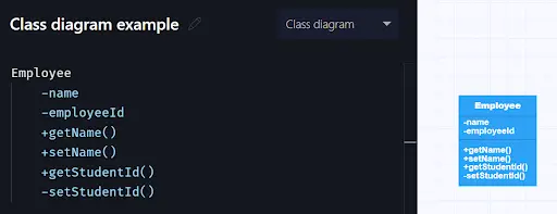
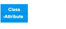
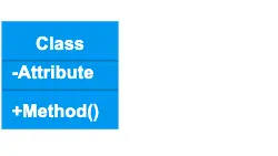
The basic elements used to create a class diagram are the class name, attributes, and methods (or operations). Classes are usually represented by a rectangle with three distinct sections separated by horizontal lines.
Class name
Each class is represented by a rectangle in the diagram, with the name of the class in the top part. Class names are usually centered, written in bold, and start with a capital letter.
Attributes
Attributes are data elements that are contained in every object of a class and have a value for each of these objects. Attributes are shown in the middle of the class rectangle, are aligned left, and the first letter is lowercase (note that it is very common to use camelCase for both attributes and methods).
Methods (operations)
Classes have particular operations for dealing with communication with other classes. Methods are shown in the bottom part of the class rectangle and, like attributes, are aligned left with the first letter in lowercase.
The visibility of both attributes and methods can be specified by means of symbols before the name. + means public, - means private, # means protected, ~means package.
If an attribute or method is derived from other values in the system, this can be indicated with a / before the name.
Both attributes and methods can also have extra parameters, such as type, initial values, and constraints.
Gleek enables you to create a class with its attributes and methods with just a few lines of the unique Gleek syntax.
Relationships
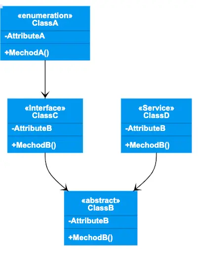
The connections between classes are called relationships. There are several different types, each shown with its own connecting line, either with or without an arrow at the end.
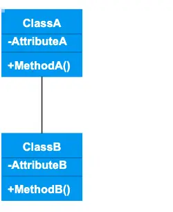
Association
Association indicates a static relationship between two classes. Association relationships will usually include text to explain the nature of the relationship.
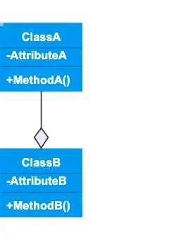
Aggregation
Aggregation shows that one or more classes are part of another class, or are contained by it. However, if all the contained classes are removed, the container will persist.
Composition
Composition is a stronger relationship than aggregation. It indicates that the classes contained depend upon the existence of the container. If the container class is removed, they cannot persist.
Related topic: Aggregation vs Composition
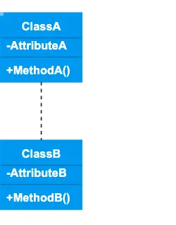
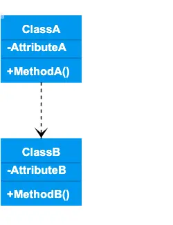
Dependency
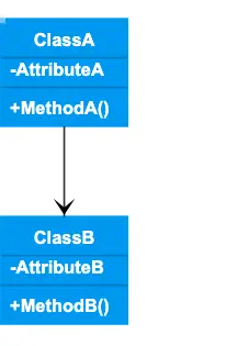
Dependency indicates that one class depends on another, in that a change in one class may result in changes in the other.
Multiplicity
Multiplicity is an association relationship and indicates that at least one of the two classes refers to the other when creating instances of itself. In other words, it shows the cardinality of the relationship.
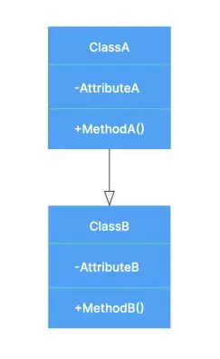
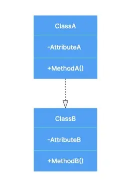
Generalization/inheritance
When a particular class is considered to be a child of another class, it will inherit the same functionalities of the parent class. The specific class provides additional properties to the parent class, but is still compatible with it.
Realization/implementation
This indicates that a particular class is responsible for the implementation of some of the functionality of another class. The relationship defines this functionality for the class that is implementing, or realizing, it.
Informal class diagrams
While class diagrams make use of UML, which is a standardized modeling language with certain conventions, they are not usually intended by developers to be formal, rigidly defined diagrams that perfectly correspond to the system being visualized or designed. They are more often used as informal tools to convey ideas and sketch out a system. That means that you are free to create whatever class diagram works for your needs.
Luckily, Gleek is a super-fast way to get your ideas out of your head and onto the screen. Read our short syntax summary, then head over to Gleek to start making a class diagram – no mouse required!
How to create a UML class diagram in Gleek
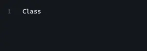
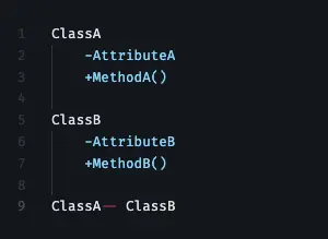
1. Create your first class. We can just name this “Class”. It will be drawn as a standard rectangle, with space for the attributes and methods.

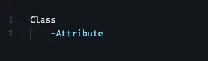
2. Add an attribute with the TAB key to indent the code.
3. Add method with TAB and add “()” at the end so that Gleek knows it’s a method!
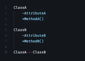
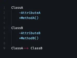
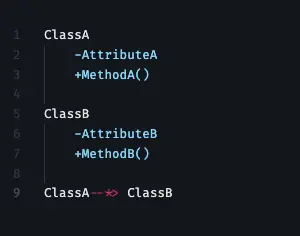
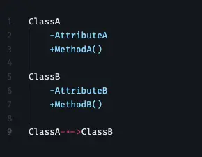
4. Now for relationships between classes. You can connect two classes with a solid line using "--"
5. Connect two classes with a dashed line using "-.-"
6. Connect two classes with an association arrow using "-->"
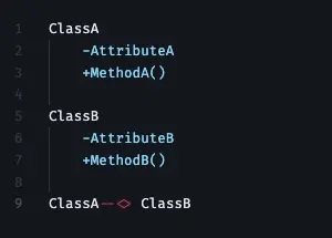
7. Connect two classes with an inheritance arrow using "--*>"
8. Connect two classes with an aggregation arrow using "--<>"
9. Connect two classes with a composition arrow using "--<*>"
10. Connect two classes with a dependency arrow using "-.->"
11. Connect two classes with a realization/implementation arrow using "-.-*>"

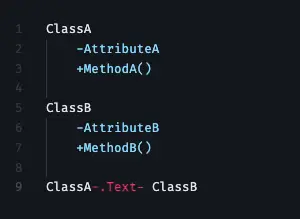
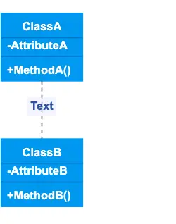
12. You can describe the connection between two classes with "-.Text->"
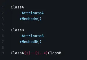
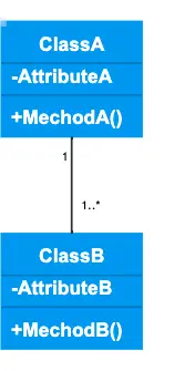
13. Assign multiplicity/cardinality using {1}--{1..*}, {0..*--{1} and so on.
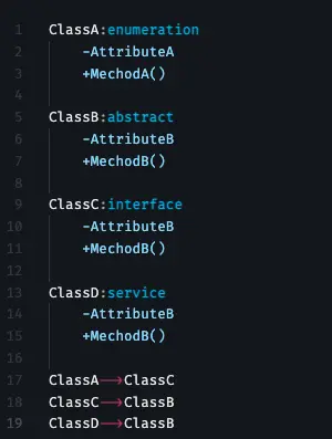
14. Finally, you can add annotation to any class with ":" and then choose one of the following standard options in Gleek: interface, abstract, service, and enumeration. How you use these will depend on your particular needs. You can also decide to stick with the standard rectangle.