
What are sequence diagrams and what are they used for?
Sequence diagrams are one of the 14 diagram types that can be created using the Unified Modeling Language (UML). UML diagrams are generally used when designing software and databases to make sure that the system will work as required and to reveal potential problems before building the final product.
A sequence diagram models the interactions between objects in a system in sequential order over time. Sequence diagrams can also be called event diagrams or event scenarios. The diagram shows how objects in the system exchange messages and which objects are active at any particular time.
Each object is shown at the top of the diagram and each has a lifeline that descends vertically from its center. This lifeline represents the object’s existence in the time period being captured. Horizontal arrows show the messages exchanged between the objects. An activation bar is a thin rectangular box that is shown on an object’s lifeline when it is active and processing a task. During this period it is said to have focus of control. Messages can go back and forth from left and right, with the sequence moving from top to bottom as the time period progresses.
Make your own UML sequence diagram with Gleek.
Sequence diagrams have traditionally been used to model interactions between computer systems, but they are increasingly used to document interactions between business objects. Business analysts can use them to model how a business currently works – by mapping out the interactions between personnel completing a task – to understand how orders are processed, or to clarify the steps involved in creating a product. This can help identify bottlenecks and streamline processes. Sequence diagrams can also be created by stakeholders to communicate requirements to developers.
Check out the best sequence diagram tools list.
What are sequence diagram fragments?
A fragment in a sequence diagram is a rectangular frame drawn over part of the diagram. They represent conditional structures that affect the flow of messages. These frames are known as combined fragments in the UML specification and the container is known as the interaction operand. The frame is labeled in the top-left corner. This label is known in UML as the interaction operator.
Let’s look at three of the most common fragments: option, alternative, and loop.
Option and alternative fragments
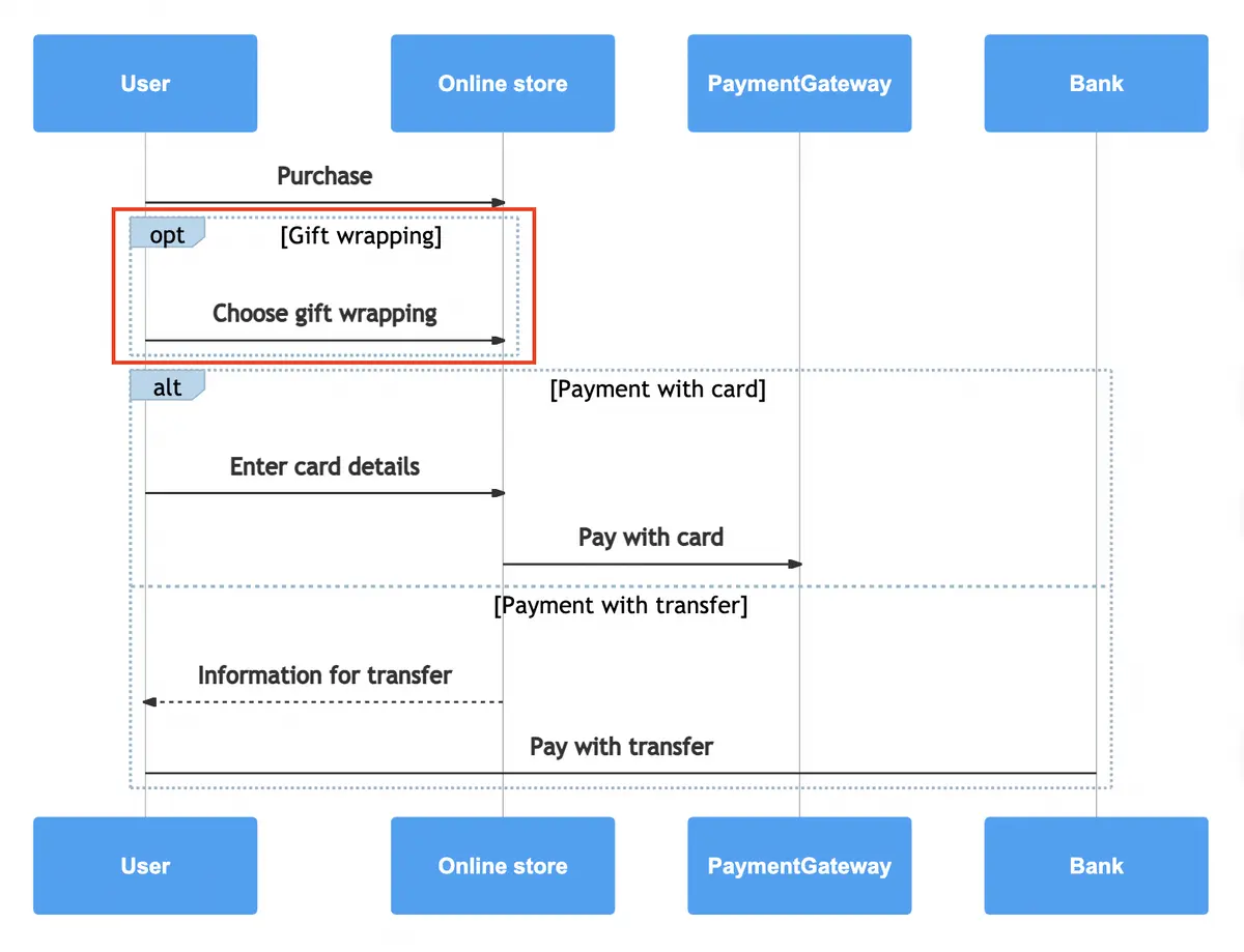
The option fragment represents a simple choice of behavior between two options. The interaction operator is opt. The sequence fragment modeled will either occur or it will not occur, based on a particular condition. For instance, a customer is presented with the option to choose gift wrapping when completing a purchase. The customer will either select gift wrapping or not.
A guard condition is optional for option fragments. Guards in UML let you check to make sure that certain conditions have been met before activating the option, such as whether the product in the online store is suitable for gift wrapping. Guard conditions are shown in square brackets at the top of the fragment frame. They are usually Boolean expressions that correspond to true or false, but in the case of the loop fragment, they can be more complex, as we’ll see a little later on.
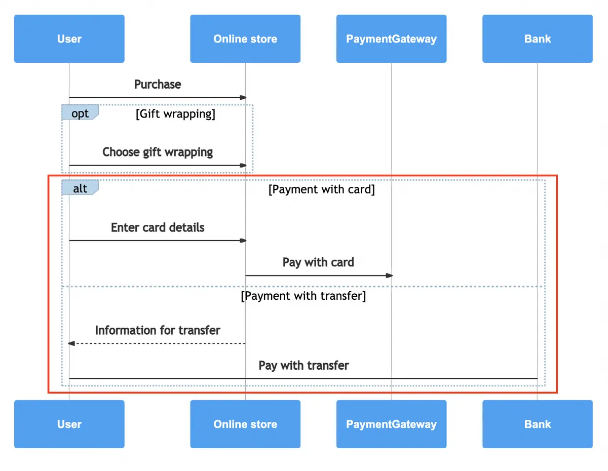
The alternative fragment models the classic if-then-else programming statement. The interaction operator is alt. In this fragment, the flow of messages depicts a mutually exclusive choice between two paths. The process flows along either one or the other path. For instance, the customer completing the purchase will either choose to pay by card or by wire transfer, not both.
An alternative combination fragment will have guard conditions that are tested against each possible operand. In our example, it might be the case that not every product can be purchased with a wire transfer.
What does a loop fragment represent?
So that’s an option and alternative fragments, but what about when you need to model something that needs to repeat a number of times? That’s when you use a loop fragment.
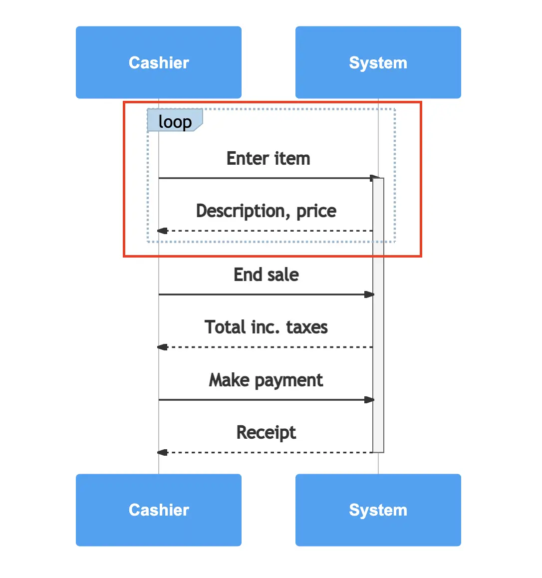
Loop fragments were introduced in UML 2 with other combined fragments and they enable you to model a repetitive sequence, along with some handy guard conditions to control the loop. The loop fragment looks much the same as the option fragment. You have the frame and the operator in the top-left corner. The interaction operator is, as you might expect, loop. For instance, a cashier entering items to be purchased into a point of sale system or a cash register may need to enter multiple items for each customer before presenting the customer with the total amount and requesting payment. So the entry of items acts as a loop fragment in the process.
As in option fragments, a guard condition can be set for loop fragments, but the guard is entirely optional. There can be a Boolean guard to test whether a condition is true or false, but guards placed on loop fragments can also have some special conditions that only apply to a loop. These cover the minimum and a maximum number of iterations for the loop, or the number of times it may be repeated. These are shown as minint = the minimum number and maxint = the maximum number of iterations. For instance, with minint=3, the loop must execute at least three times. If the same loop has maxint=9, it cannot execute more than nine times.
Make your own UML sequence diagram with Gleek.
You should now have a solid understanding of how loop fragments can help you create a sequence diagram that can represent repetitive interactions between objects. Remember that the unique Gleek syntax makes it easy to create sequence diagrams without even using a mouse, so head over to gleek.io and create a loop fragment right now!
Related posts
System Sequence Diagrams vs. Sequence Diagrams in UML
Sequence diagram for ATM withdrawal: a step-by-step guide
Sequence diagram for microservices with Gleek AI
How to create a user login sequence diagram
Top 8 UML sequence diagram tools