
What is a sequence diagram and what is it used for?
Sequence diagrams show an overview of the interactions between objects in a system over time. Also called event diagrams or event scenarios, sequence diagrams depict the sequential events that occur and the processes that are completed.
Sequence diagrams descend from top to bottom to show the sequence of interactions. The objects, or actors, are shown at the top of the diagram as named rectangles.
Each object has a vertical lifeline descending from it to show the different processes that exist simultaneously in the system during the time period captured by the diagram.
The interactions between them are represented by horizontal arrows that can go from left to right and vice versa. These arrows actually depict messages in the system and the style of arrow tells you whether the messages are synchronous, asynchronous, or whether the message creates or deletes objects in the system. The arrows descend in the order in which the events they represent occur.
You can depict complex interactions between multiple objects in the sequence diagram by using sequence fragments. These act as frames for parts of an interaction. The fragment is marked by an operator in the top-left corner. The operator might be alt/else, if there is a choice between multiple operands, opt, if there is a choice between two operands, and the condition is either met, or not met. These guard conditions are interaction constraints that divert the flow of events depending on particular circumstances, such as whether a user has supplied the correct password. We will use the alt operator in our example below.
You can read more about the other types of messages and operators used in sequence diagrams in our detailed breakdown of how sequence diagrams work.
Example: how to create a sequence diagram for an ATM withdrawal
Sequence diagrams are great at showing the interactions between elements in a system over time. An example might be how a banking client interacts with an ATM to withdraw cash.
So let’s draw an ATM withdrawal in the form of a sequence diagram using Gleek.io.
Make your own UML sequence diagram with Gleek.
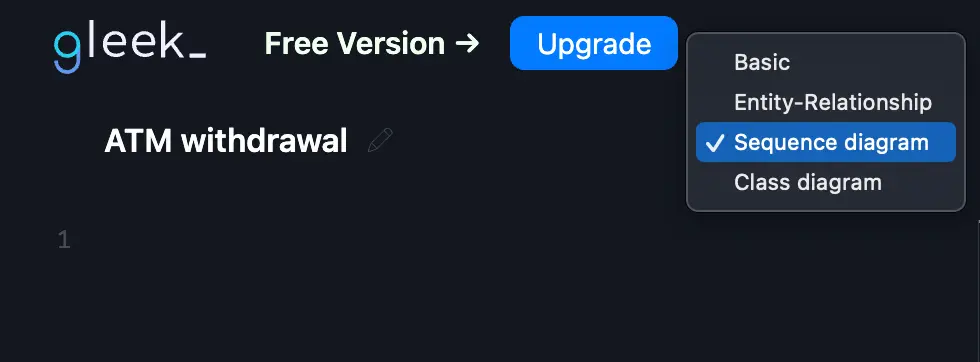
Open up the Gleek.io app and select “sequence diagram” from the dropdown menu in the code field. Select the existing example code and delete it so that you can start fresh. You might like to rename “Welcome diagram” to something else. Something like “ATM withdrawal”.
We can start by considering the actors we’ll use. In our example, we need to represent the user, the ATM, and the database. We don’t need to define these objects yet. They will automatically be created as we describe the interactions.
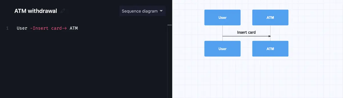
The first interaction is simple. The user inserts the bank card into the ATM.
User -Insert card-> ATM
Type “user” and then create a labeled arrow to explain the message that is going from the user to the ATM. Just hit the hyphen key, then type the label “insert card” and Gleek.io will automatically understand that you’re creating a message. After entering the label, just autocomplete the arrow to complete your first interaction.
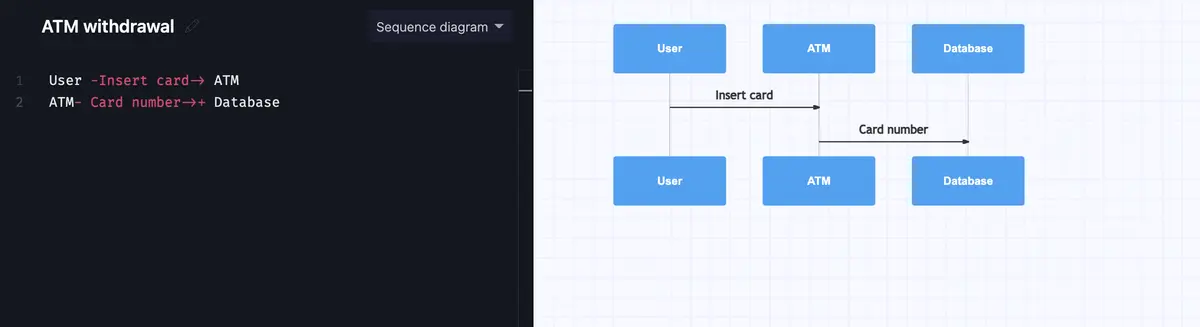
Next, the ATM needs to check the bank database to make sure that the card number is valid. We’ll describe this message with syntax that will create an activation bar, to show that the database object is active, or instantiated, during this period of the process.
Check out our latest tutorial on How to create a Sequence diagram for Microservices using Gleek AI chat.
So we again type the syntax to create a message between ATM and database labeled “card number” and autocomplete the arrow. This time, we need to hit the plus key to add an activation bar to the diagram.
ATM- Card number->+ Database
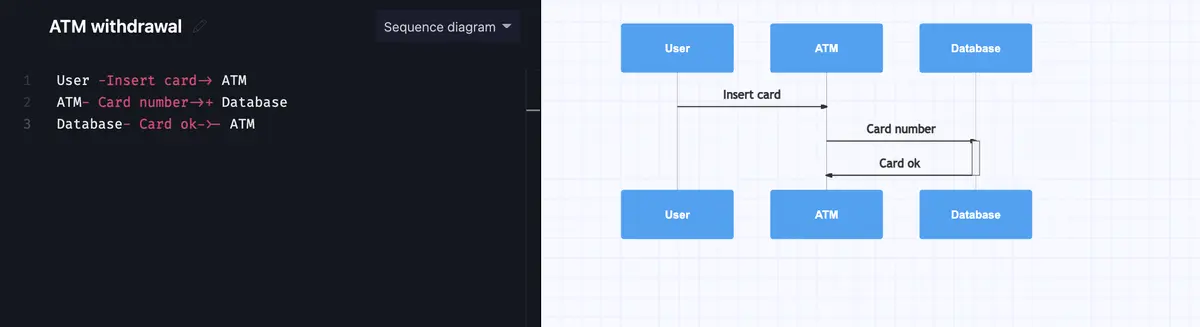
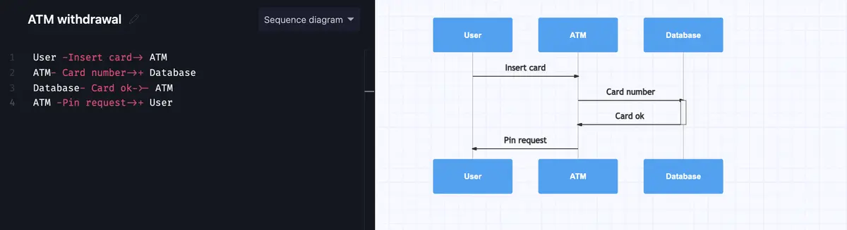
This is a reply message, as the database will send a response back to the ATM. To represent this in Gleek.io, just add a hyphen after that arrow in the “card OK” message that the database sends to the ATM. The hyphen acts as a minus sign, in this case, to terminate the activation bar so that the message will be sent back at the end of the activation bar.
Database- Card ok->- ATM
The ATM now needs the user to enter their PIN. This is a simple case of messages from the ATM to the user and from the user to the ATM. Again, we’ll add a plus at the end to show activation bars and indicate which object is instantiated.
ATM -Pin request->+ User
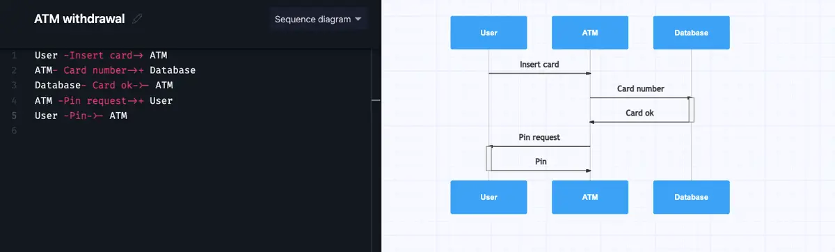
The user enters the PIN and the information is transmitted to the ATM.
User -Pin-> ATM
Make your own UML sequence diagram with Gleek.
Now the ATM again has to check the database to make sure that the PIN is correct. Don’t forget the plus sign!
ATM -Check pin->+ Database
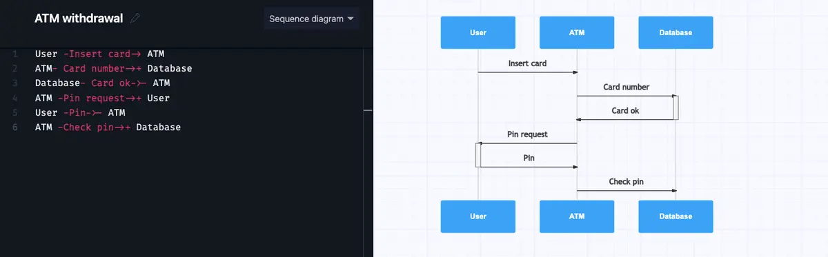
The database checks that the PIN is correct and sends a message back to the ATM.
Database- Pin is correct->- ATM
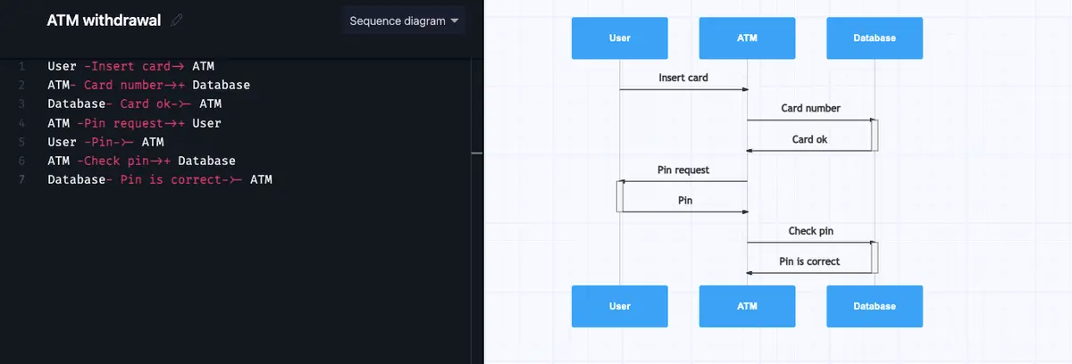
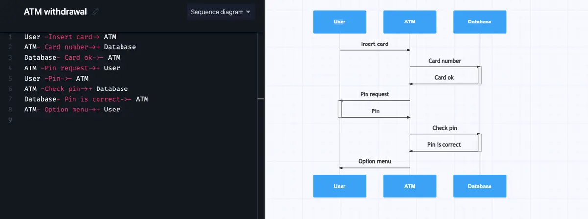
At this point, the user needs to decide what they want to do, so the ATM presents the user with an option menu.
ATM- Option menu->+ User
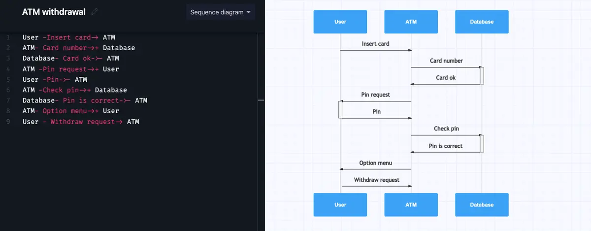
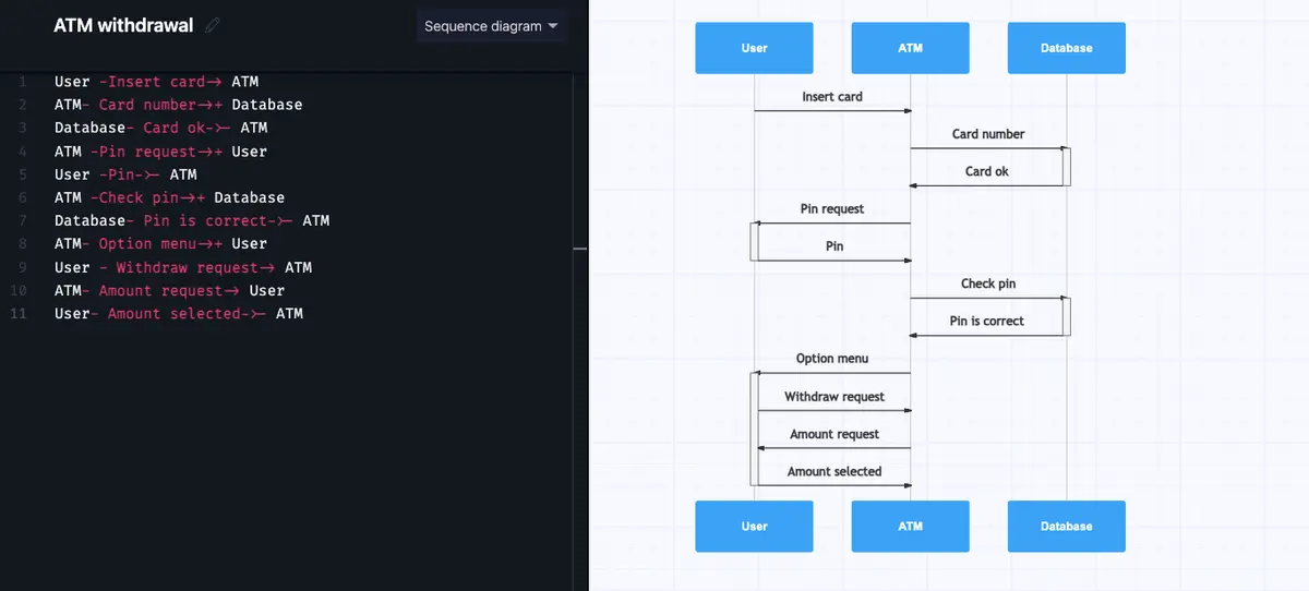
The user sends a request to withdraw cash. Then there is some back and forth with the ATM asking and the user selecting the amount to withdraw. Note that the activation bar stays with the user throughout this interaction.
User – Withdraw request-> ATM
ATM- Amount request-> User

User- Amount selected->- ATM
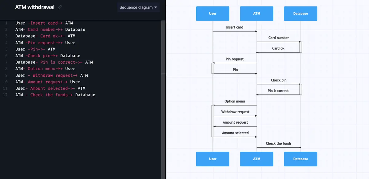
Once the amount has been selected, the ATM needs to send a message to the database to check that there’s enough money in the customer’s account. Note that the activation bar is also terminated.
ATM – Check the funds-> Database
There are two possible responses to this message. In one, the user has enough funds and can withdraw the money. In the other, the user does not have enough funds and the request is denied.
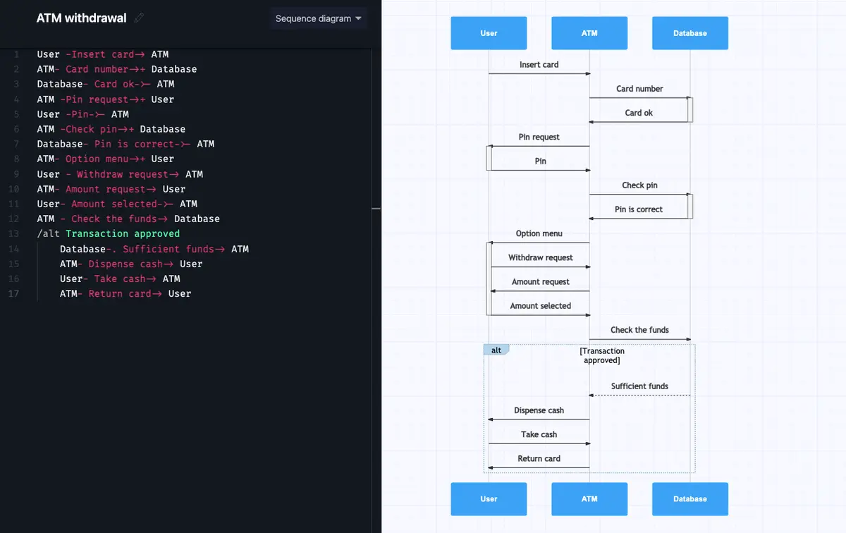
We represent this by using an alt operator. Just use forward slash and type alt to get this working in Gleek.io and add a description for the condition you want to represent. The first scenario we will describe is when the transaction is approved.
/alt Transaction approved
Gleek.io will frame this fragment of the process. It’s important that you hit the TAB key after each line when you’re creating this frame. This indents each line and nests the whole section in the frame.
Make your own UML sequence diagram with Gleek.
The database’s response to the ATM in the case that there are sufficient funds is a response message. You can show this by using an arrow with a dotted line. Just add a period after the hyphen to do this.
Database-. Sufficient funds-> ATM
Remember to use the TAB key to indent the line!

If the user has enough money in their account, the ATM will dispense the cash, the user will take the cash, and finally, the ATM will return the card (or in some cases, the card will be returned before the cash).
ATM- Dispense cash-> User
User- Take cash-> ATM
ATM- Return card-> User
But our sequence diagram doesn’t end there. Sadly, the user might not have enough money in their account. In this case, we continue the alt fragment and follow through to the user getting a rejection message and receiving their card, but no cash.
/alt Transaction rejected
Database- insufficient funds-> ATM
ATM- Show rejection details-> User
ATM- Return the card-> User
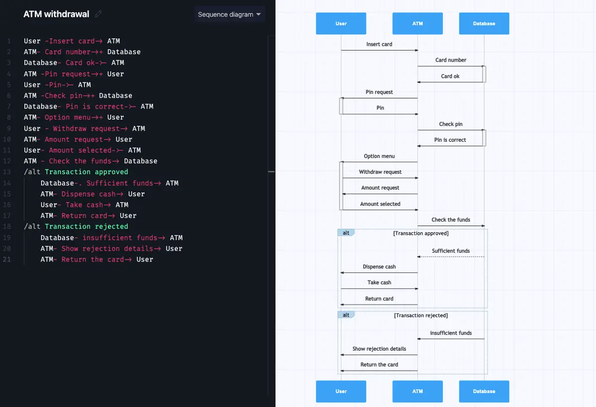
So our imaginary user might leave the ATM empty-handed, but we hope that you leave this example with a clear understanding of how to create a simple sequence diagram in Gleek.io!
Related posts
Sequence diagram for microservices with Gleek AI
How to create a user login sequence diagram
Streamlining APIs with Sequence Diagrams
Sequence diagram for library management system
Top 8 UML sequence diagram tools