What is UML?
Developers often use the Unified Modelling Language (UML) when designing software. UML is not a programming language, but a visual diagramming language that uses standardized models and diagrams to represent the design of the system. It was created to help software engineers and system designers better understand each other’s needs when cooperating on developing complex systems. UML originates from the mid-1990s and has been evolving and changing ever since.
What is an object diagram?
Object diagrams are a particularly concrete form of UML diagram, as they represent a view of a system at a discrete point in time. They show the real-world instances of the objects in the system at that point and the relationships between these instances. The object diagram can focus on part, or show a complete view of the system being modeled.
An example should clearly illustrate the relationship. In a class diagram representing a grocery store, any possible product might have the following attributes: category, name, quantity, expiry date. In the object diagram of the same store, a particular instance of that product can be more concretely represented as: category: dairy; brand: Elysian Farms; name: Fresh Organic Milk; quantity: 1 liter; expiry date: March 8, 2021.
Object diagrams are therefore closely related to and dependent on creating accurate class diagrams. You can even think of the object diagram as a way of taking your class diagram for a test drive to make sure that everything works the way you expect.
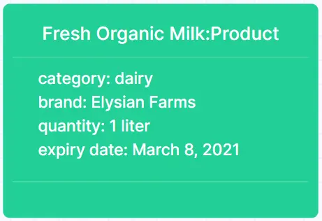
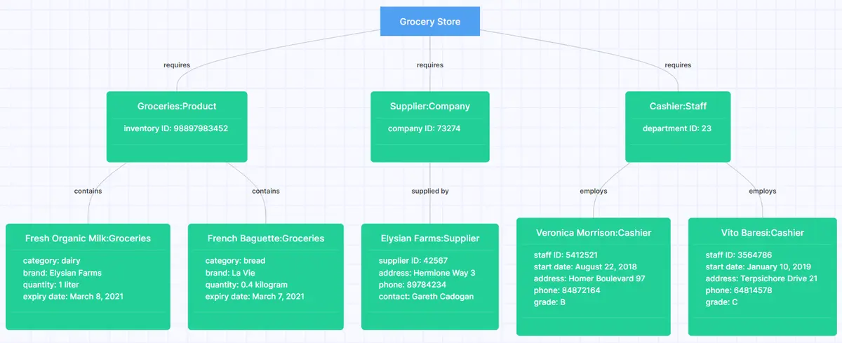
The elements used in an object diagram are very straightforward. Rectangles represent each instance of an object, with its name and class at the top, separated by a colon. The attributes of the instance are shown under a line, along with their values.
Going back to our grocery-inspired example, the milk can be represented like this in Gleek:
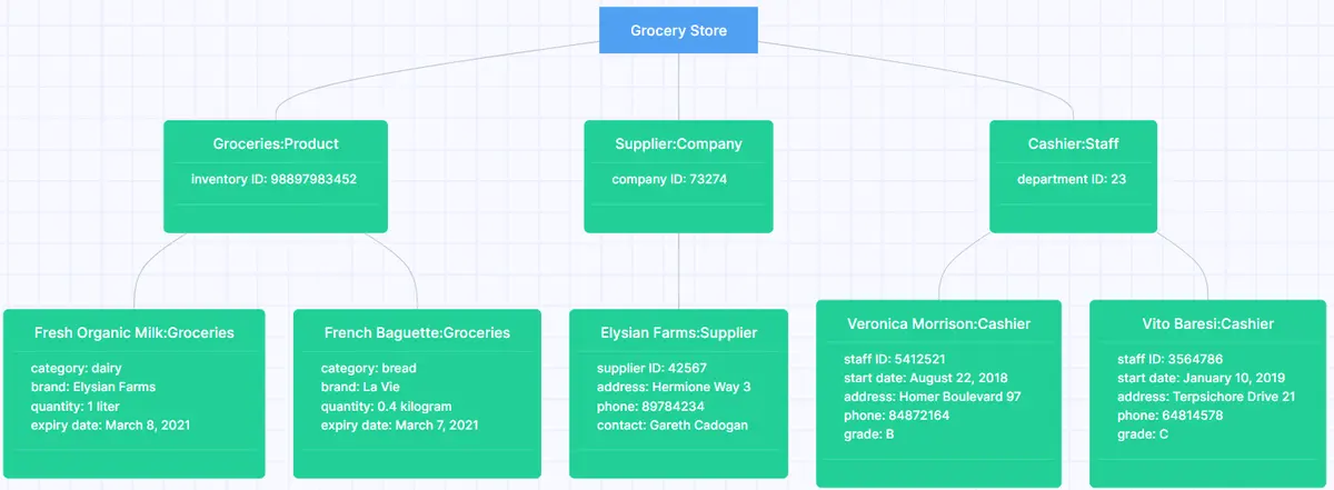
Object diagrams also show the relationships between instances using lines, or links. For instance, our grocery store might have the following relationships once you add more products, departments and companies.
UML diagrams can be drawn in a formal or an informal way. A formal UML diagram is quite restrictive and requires you to use standard symbols and icons. In the real world, you often just want to create an object diagram that will let you sketch out and communicate your ideas.
For that, it is usually enough to use an informal approach. You can then rely on just lines to link your objects, labeling them to indicate the nature of the relationship. For instance, our grocery store diagram could be made clearer if we added labels:
How to draw an object diagram in Gleek
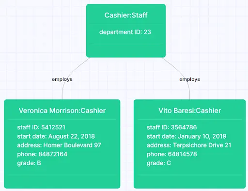
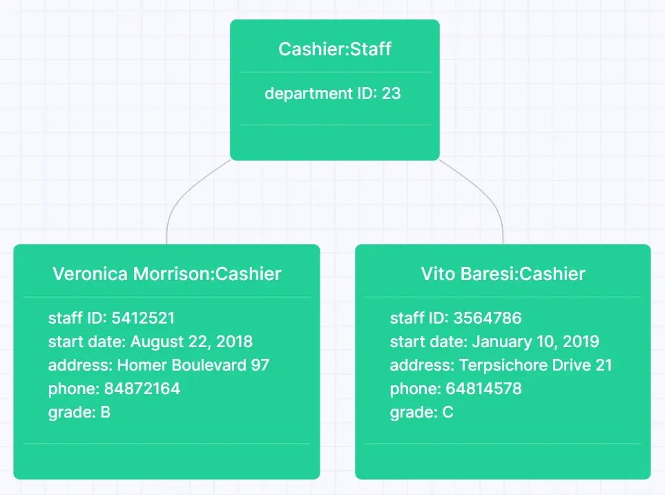
Remember that you don’t have to diagram an entire system. You can focus on whatever part you want to test. Let’s say that we want to explore the structure of our cashier department from the example above.
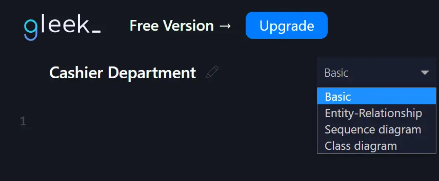
1. First open up Gleek and select “Basic” in the dropdown for diagram type. You can also rename the diagram by clicking on the pencil icon.
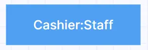
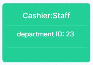
2. We can then create an object to represent the department. We just have to type “Cashier:Staff” and a rectangle will be created, ready for any attributes to be added.

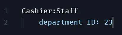
3. Let’s add an attribute to the object. It’s a department, so it will need a department ID. Hit Enter after the name and then TAB to indent the attribute. Our department ID can be 23.
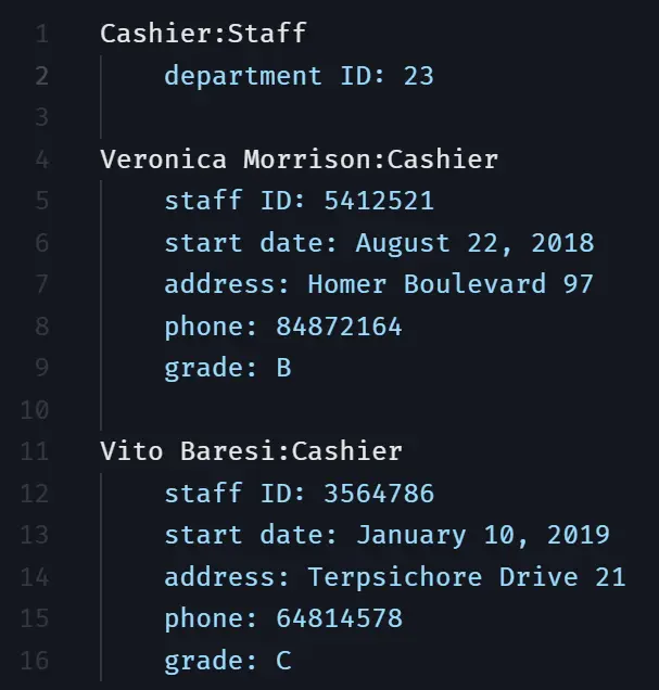
4. Now we need our staff. Do the same for each of them, with their names separated from their class by a colon.
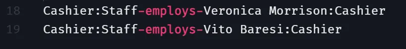
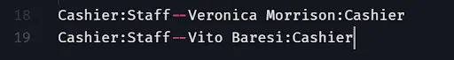
5. To add a simple link between the department and its employees, you just need to enter the following short extra lines of text in the Gleek code field. Gleek will autocomplete any objects you have already created as soon as you start typing and then you can connect them using "--".
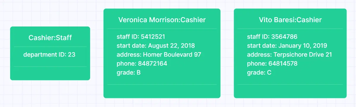
And Gleek will then automatically rearrange the objects in your diagram. Gleek can do this for as many elements as you need to add, so you don’t need to waste time aligning boxes and moving things around with the mouse 🐁🚫⌨️💪
6. Finally, we can add a simple label to show the relationship between the department and its cashiers. Just put your cursor in between your "--" and type the word that best represents the relationship. For our example, “employs” works well.